EasyManuals Logo

Rotax 912 i series Service Manual

Rotax 912 i series
168 pages
To Next Page IconTo Next Page
To Previous Page IconTo Previous Page
Page #70 background imageLoading...
Page #70 background image
BRP-Rotax
MAINTENANCE MANUAL LINE
Step
Procedure
5
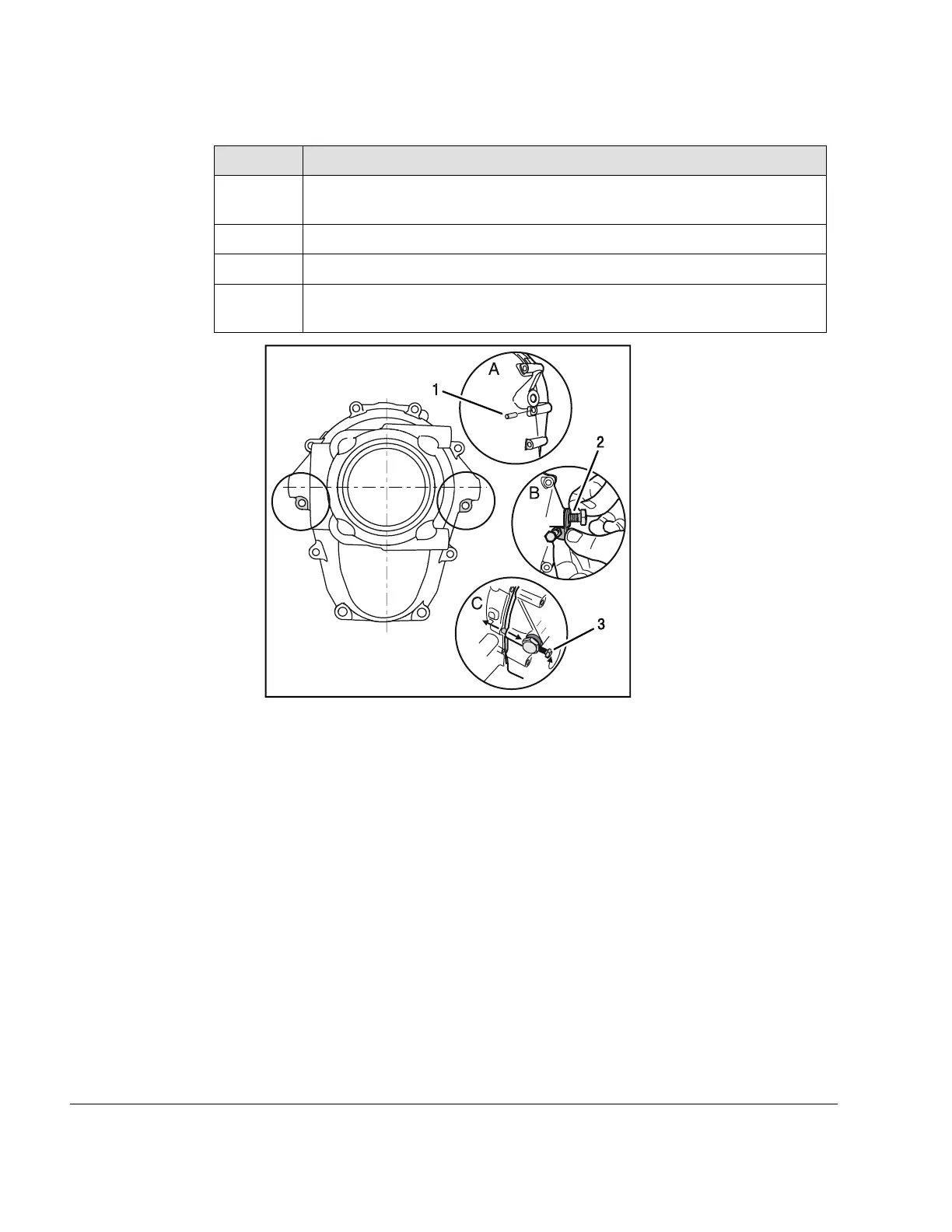
Insert the dowel pin 8x20 into the bore on the right and left of the gearbox
housing.
6 Install hex. screw M6x40 into the pushing jig assy.
7
Put the pushing jig assy. in the center and fix it with a hex. screw M10x20.
8 Using the hex. screw, press the gearbox housing off from the crankcase si-
multaneously on the right and left.
09560
1
2
3
Figure 5.3
1
Dowel pin 8x20
2 Hex. screw M10x20
3 Hex. screw M6x40
05–50–00
Page 4
September 01/2018
Effectivity: 912 i Series
Edition 2/Rev. 0

Table of Contents

Other manuals for Rotax 912 i series

Questions and Answers:

Question and Answer IconNeed help?

Do you have a question about the Rotax 912 i series and is the answer not in the manual?

Rotax 912 i series Specifications

General IconGeneral
Number of Cylinders4
Max Power100 hp (73.5 kW)
Max Power Output RPM5800 rpm
Ignition SystemDual electronic ignition
Oil SystemDry sump, forced lubrication with separate oil tank
Reduction Gear Ratio2.43:1
TBO2000 hours
Engine Type4-stroke, horizontally opposed
Displacement1352 cm³
Bore x Stroke84 mm x 61 mm
Max Torque128 Nm
Fuel TypeAvgas 100LL or unleaded automotive gasoline
Fuel SystemElectronic fuel injection
Cooling SystemLiquid/air-cooled

Related product manuals