BRP-Rotax
Maintenance Manual
72-00-00
page 26
May 01/2007
Effectivity 912/914 Series
Edition 1 / Rev. 0
d02622
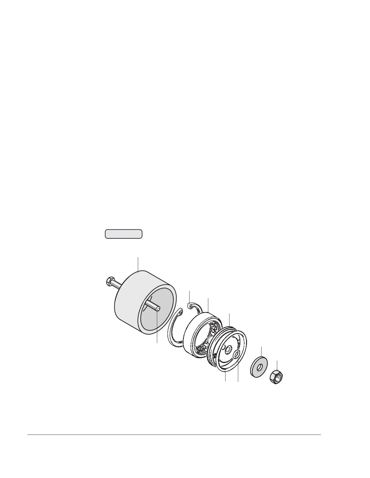
3.9.2) Removal of roller bearing for - Series 3
See Fig. 72-23.
After the propeller gearbox is removed, the crankcase side propeller
shaft bearing and oil inlet flange can be replaced if necessary.
Before disassembly, the governor flange must be removed. On
configuration 912 Series 3 with hydraulic governor, the procedure for
pressing out varies from that for Series 2 and 4. On Series 3, the roller
bearing is pressed out together with the oil inlet flange.
Remove the retaining ring (1) with circlip pliers. Fit puller cap (2), part
no. 876489, and push hex. screw (3) through the cap, roller bearing (4)
and oil inlet flange (5). Fit washer (6) and nut (7) on the back end. By
turning the hex. screw clockwise, the roller bearing is pulled out
together with the oil inlet flange. Take out O-ring (8) and both O-rings
(9).
00249
8
9
1
2
3
4
5
6
7
Fig. 72-23

 Loading...


