EasyManuals Logo

Rotax 914 series Maintenance Manual

Rotax 914 series
456 pages
To Next Page IconTo Next Page
To Previous Page IconTo Previous Page
Page #303 background imageLoading...
Page #303 background image
Effectivity 912/914 Series
Edition 1 / Rev. 0
74-00-00
page 55
May 01/2007
d02624
BRP-Rotax
Maintenance Manual
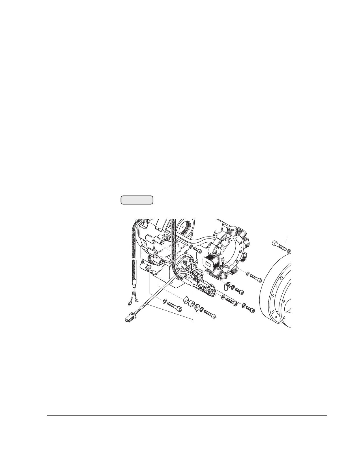
3.22) Rev counter and ignition trigger coils
See Figs. 74-36 and 74-37.
â—† NOTE: All 5 trigger coils are of equal design. Therefore this checking
procedure is valid for the ignition trigger coils too.
The rev counter trigger coil (3) is fitted on the ignition housing.
- Inspect for physical damage.
- Inspect all connections
â–  CAUTION: Any parts which have suffered physical damage or are not
functioning correctly must be replaced without delay. For mea-
surement values, see 74-00-00 sec. 3.12.
00094
3
Fig. 74-36

Table of Contents

Other manuals for Rotax 914 series

Questions and Answers:

Question and Answer IconNeed help?

Do you have a question about the Rotax 914 series and is the answer not in the manual?

Rotax 914 series Specifications

General IconGeneral
Bore79.5 mm
Stroke61 mm
Compression Ratio9.0:1
Cooling SystemLiquid-cooled cylinder heads, air-cooled cylinders
Redline5800 rpm
Engine Type4-cylinder, 4-stroke
Fuel TypeAvgas 100LL
Oil SystemDry sump
Fuel Systemfuel injection
TBO (Time Between Overhauls)2000 hours
Displacement1.211 liters (1211 cc)
Power Output84.6 kW (115 hp) at 5, 800 rpm

Related product manuals