76-00-00
page 32
May 01/2007
Effectivity 914 Series
Edition 1 / Rev. 0
d02626
BRP-Rotax
Maintenance Manual
3.1.2) Static check of the turbocharger control
The easiest way to check function of turbocharger control components
is by the communication program. If this program is not at your
disposal, the following static checks can be carried out.
◆ NOTE: Visual inspection of all components.
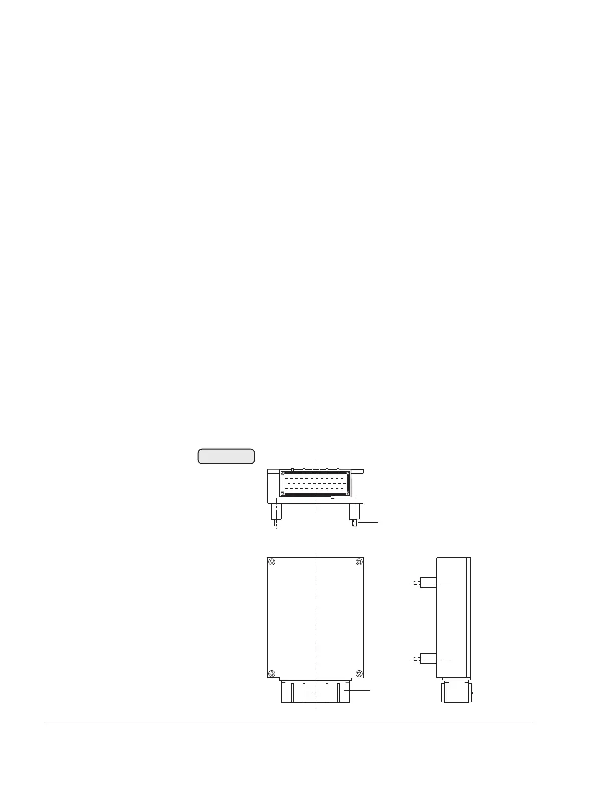
3.1.2.1) Turbo control unit (TCU)
See Fig. 76-29
Location of installation may vary depending on aircraft model
and is limited by the length of the wiring harness.
- Inspection for physical damage.
- Inspection of the 4 rubber buffers (1) for damage, which is
detrimental for vibration damping.
- Inspection of the 36-pin plug receptacle (2).
▲ WARNING: The TCU must never be opened.
■ CAUTION: Replace TCU without delay in the event of
physical damage or incorrect operation.
1
00092
2
Fig. 76-29

 Loading...


