Effectivity 914 Series
Edition 1 / Rev. 0
79-00-00
page 21
May 01/2007
d02628
BRP-Rotax
Maintenance Manual
00075
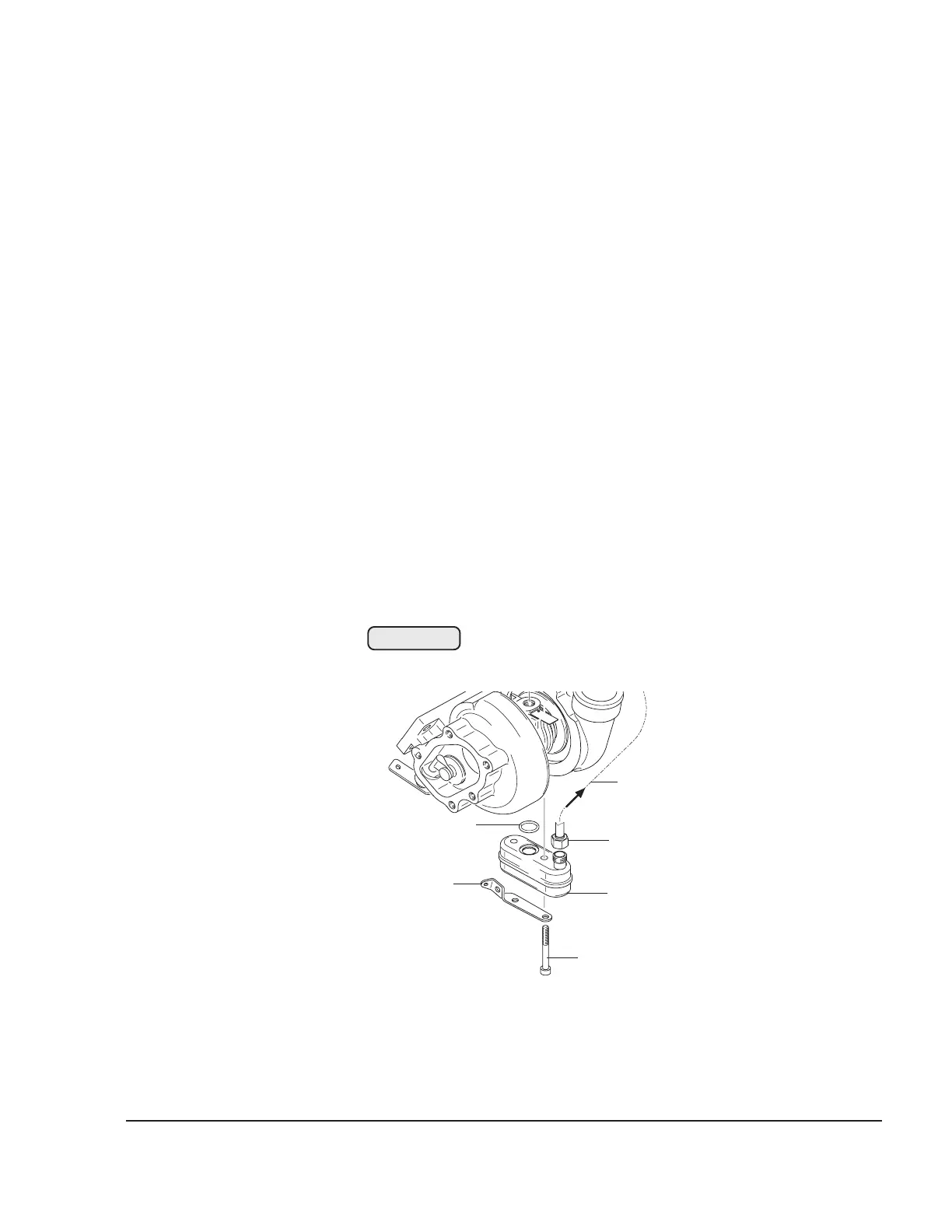
3.3) Oil sump (only on 914 Series)
See Fig. 79-15
◆ NOTE: The oil sump (1) is only removed in the event of damage or for
cleaning.
Remove tension spring from wastegate flap with a suitable tool.
Release collar nut (2) of the turbo oil suction line (3). Remove the 2 allen screws
(4) M6x55 and take off cable support (5), oil sump (1) and O-ring (6) 9x2.3.
Clean all components and check them visually. Also check thread and flange
surface of turbo charger housing. In the event of damage, replace oil sump.
Reassembly in reverse order.
The oil sump (1) is attached with the O-ring (6), cable support (5) and 2 allen
screws (4) M6x55.
Tighten collar nut (2) of the turbo oil suction line to 20 Nm (180 in.lb).
Secure the allen screws (4) with wire.
Fig. 79-15
6
1
2
3
4
5

 Loading...


