Effectivity 912/914 Series
Edition 1 / Rev. 0
74-00-00
page 15
May 01/2007
d02624
BRP-Rotax
Maintenance Manual
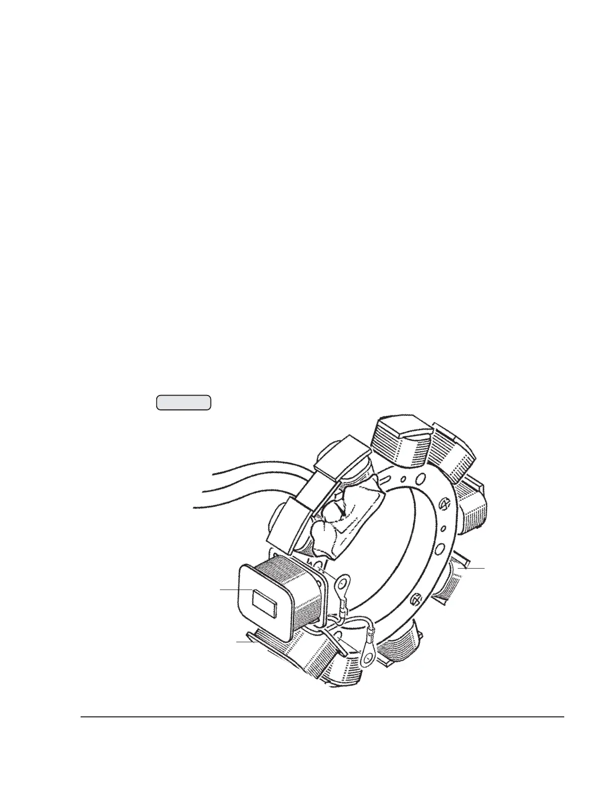
3.6) Charging coil
See Fig. 74-12.
In case of malfunction of one ignition circuit, the 2 single-pin plugs of the red
charging cables may be interchanged for localization of the problem.
If the failure remains on the same ignition circuit, the electronic module is the
cause and the respective module must be replaced see 74-00-00 sec. 3.5.
If the failure passes on with the ignition circuit, the charging coil (1) for ignition
circuit "A" or (2) for circuit "B" is the cause. In this case the stator must be
removed see 74-00-00 sec. 3.19
Check charging cable for damage. Measure resistance with a multimeter see
74-00-00 sec. 5, if necessary, replace the complete stator. See 74-00-00 sec.
3.12.
Fig. 74-12
1
2
3
00400

 Loading...


