BRP-Rotax
Maintenance Manual
72-00-00
page 10
May 01/2007
Effectivity 912/914 Series
Edition 1 / Rev. 0
d02622
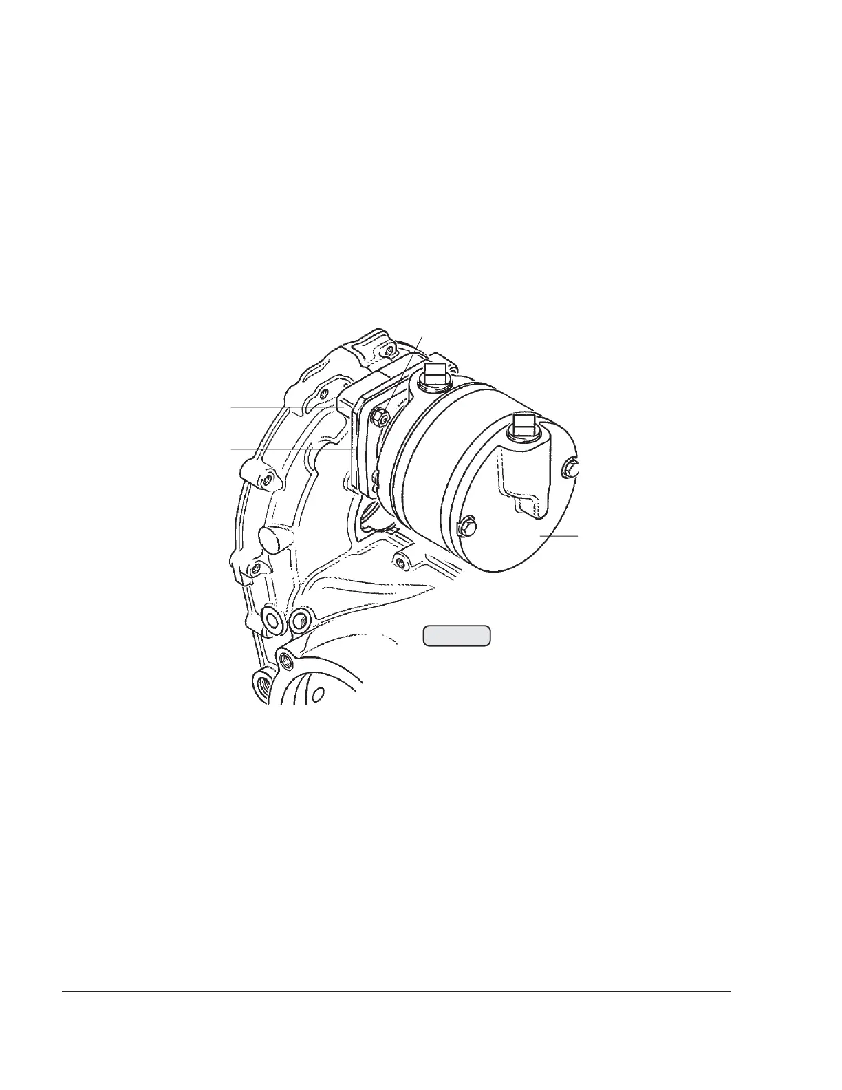
3.2) Vacuum pump removal and inspection
See Fig. 72-4.
■ CAUTION : Observe the vacuum pump manufacturers specifications for
maintenance, inspection and repairs!
Unscrew the 4 hex. nuts (1) M6 and remove the lock washers. Remove the
vacuum pump (2) from the crankcase (4) together with the gasket and the
retaining flange (3).
3.3) Governor removal and inspection
See Fig. 72-34 in 72-00-00.
■ CAUTION : Observe the governor manufacturers specifications for mainte-
nance and repairs!
Unscrew the 3 allen screws (16) M8x40 and the 1 allen screw (17) M8x35 and
remove together with the lock washers. Remove the governor with the gasket.
◆ NOTE: The screwing can be different depending on the type of gover-
nor. See SB-912-052 and/or SB-914-035, “ Installation / Use of
governor“, latest issue.
Fig. 72-4
00251
1
2
3
4

 Loading...


