EasyManuals Logo

Rotax 914 series Maintenance Manual

Rotax 914 series
456 pages
To Next Page IconTo Next Page
To Previous Page IconTo Previous Page
Page #316 background imageLoading...
Page #316 background image
75-00-00
page 4
May 01/2007
Effectivity 912/914 Series
Edition 1 / Rev. 0
d02625
BRP-Rotax
Maintenance Manual
2.2) Connections for instrumentation
â–  CAUTION: Consult also the relevant sections on connections for instru-
mentation in the latest Installation Manual.
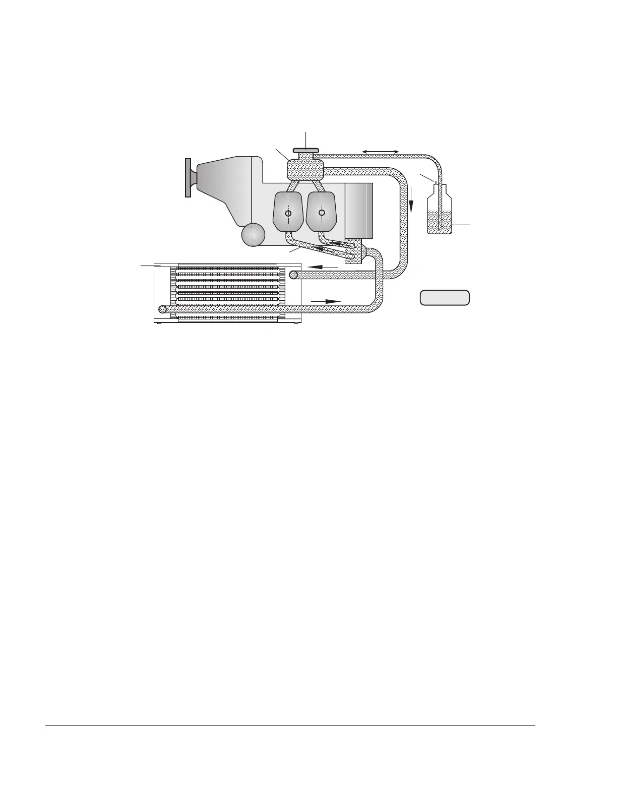
2.2.1) Cylinder head temperature display
There are temperature sensors screwed in to the cylinder heads of
cylinders 2 and 3. They monitor the material temperature of the head,
not the coolant temperature. The temperature sensor can be con-
nected to a indicating instrument and/or a temperature warning switch.
Fig. 75-1
00125
6
1
2
3
4
5

Table of Contents

Other manuals for Rotax 914 series

Questions and Answers:

Question and Answer IconNeed help?

Do you have a question about the Rotax 914 series and is the answer not in the manual?

Rotax 914 series Specifications

General IconGeneral
Bore79.5 mm
Stroke61 mm
Compression Ratio9.0:1
Cooling SystemLiquid-cooled cylinder heads, air-cooled cylinders
Redline5800 rpm
Engine Type4-cylinder, 4-stroke
Fuel TypeAvgas 100LL
Oil SystemDry sump
Fuel Systemfuel injection
TBO (Time Between Overhauls)2000 hours
Displacement1.211 liters (1211 cc)
Power Output84.6 kW (115 hp) at 5, 800 rpm

Related product manuals