A4US
US
A4
US A4
US
A4
A4 US
US
A4
US
A4
A4 US
IQ3 Full Configuration Manual – Section: Settings 27
2.3.2-8 Control – Remote – Profibus
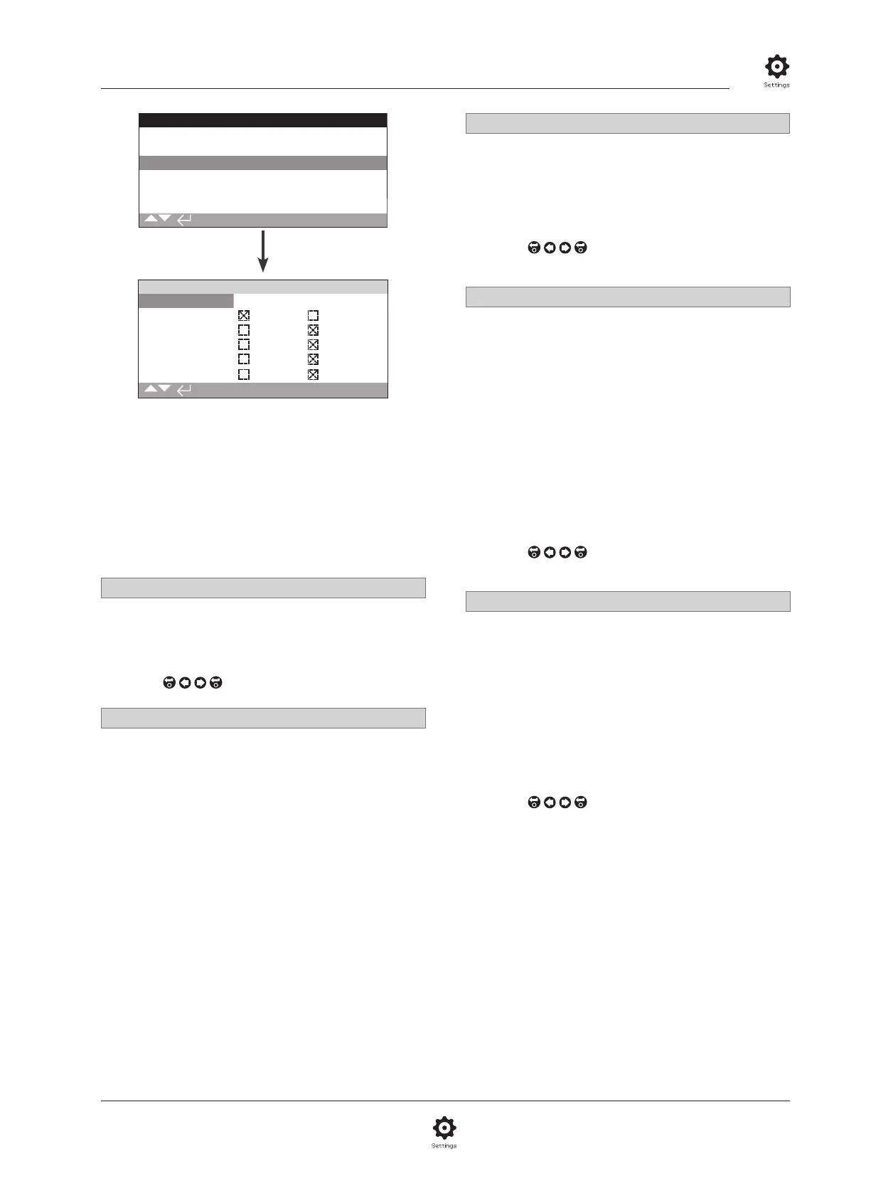
Remote Control
Analogue
Pakscan
Profibus
HART
Modbus
Extra I/O
Profibus
Address 126
GSD Param. Yes No
Termination1 On Off
Termination2 On Off
Redundancy Flying System
Extended Diag. Yes No
1/6
The Profibus Control option settings page is shown above
with its default settings. Profibus is a control option and
is available in single or dual versions, refer to wiring
diagram.
Depending on the Profibus control scheme, other related settings
may be required, refer also to:
2.3.2-4 Positioning
2.3.2-5 Auxiliary Mask
1/6 Address
The actuator Profibus module must be allocated a unique
address in the Profibus system. Changes made to the address will
take effect immediately. The range of address is 1 – 126 (default
126). Refer also to 5/6 Redundancy.
To change,
. The set address will be indicated.
2/6 GSD Parameter
If the user parameterisation data is to be setup using FDT, EDDL
or the actuators menu, setting this menu item to No will ensure
that the user parameterisation data sent to the Profibus card
during the parameterisation of the Profibus network with the
GSD file will be ignored. The settings previously made will not
be overwritten. As default this is Yes to ensure that the Profibus
card will be parameterised by the GSD user parameterisation
data.
Yes (default) – Parameterisation by GSD file is enabled.
No – Parameterisation by GSD file is disabled.
3/6 - 4/6 Termination 1 - Termination 2
Profibus networks require active termination at each end of the
highway. Profibus option has active termination (2 sets for dual)
built in, which can be switched in or out of the circuit.
Off (default) - Termination resistors switched out.
On – Termination resistors switched in.
To change,
. The checkbox will indicate the set
termination mode.
5/6 Redundancy
Used for dual Profibus option (redundant) only. Refer to wiring
diagram.
System (default) - System redundancy means that there are 2
completely separate Profibus highways in the network system
and that each highway is connected to one of the Profibus
channels. In this mode the address of both Profibus channels are
identical.
Flying - Flying redundancy means that there is 1 highway that is
connected to both channels, in this mode the addresses of the
channels must be different to avoid both channels responding to
the same message. In flying redundancy channel 2 address will
be channel 1 address plus 64.
If flying redundancy is used, the address for 1/6 must not
be set higher than 62.
To change,
. The checkbox will indicate the set
redundancy.
6/6 Extended Diagnostics
Used for dual Profibus option (redundant) only. Refer to wiring
diagram.
The slave redundancy specification from the PNO describes
extended diagnostics that are available in the redundant card.
These messages describe, for example, the state of the backup
channel. Diagnostics messages can be turned on and off
depending on the capabilities of the PLC to which the module is
connected.
No (default) - Diagnostic messages turned off.
Yes - Diagnostic messaging turned on.
To change,
. The checkbox will indicate the set
extended diagnostic mode.