RTK Series 725 Annunciator
11
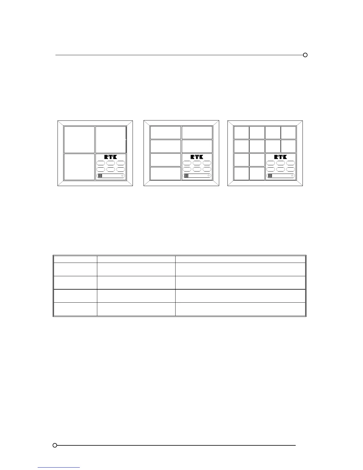
3.6 Window Numbering System
RTK have adopted the following window numbering system to aid with the location of the film legend
and the associated alarm cards. This method is used to ensure that the legend matches the functions
selected for the designated alarm.
SYSTEM
TEST
FIRST
RESET
7
MUTE
POW ER
RESET
1
5
3
ACK
LAMP
TEST
RESET
FIRST
RESET
6
2
3
4
LAMP
TEST
ACK
MUTE
SYSTEM
TEST
POW ER
1
5
FIRST
RESET
RESET
2
SYSTEM
TEST
POWER
MUTE
ACK
LAMP
TEST
1
3
6
8
4
2
12
10
9
11
Medium Window Version
Small Window Version
Large Window Version
3.7 Alarm Card Types
There are 4 basic types of dual channel alarm cards
PART NO DESCRIPTION USED ON
CB5674POP1
2 Channel alarm card
(Without repeat relays)
Large, medium and small window versions
Locates in the upper slot of the associated cell
CB5674POP2
2 Channel alarm card
(With repeat relay facility)
Large, medium and small window versions
Locates in the upper slot of the associated cell
CB5674POP3
2 Channel alarm card
(Without repeat relays)
Small window versions
Locates in the lower slot of the associated cell
CB5674POP4
2 Channel alarm card
(With repeat relay facility)
Small window versions
Locates in the lower slot of the associated cell
Card types are supplied suitable for operation from one of the following signal supply voltages 24V,
48V, 125V or 250V. These voltages are shown on the individual alarm card and X is used to indicate
which version has been supplied. Alarm cards are plugged into the rear of the annunciator and once
inserted automatically connect to a pre-tested passive display motherboard.
3.8 Pushbutton / Programming Module
The pushbutton/programming module is located in the bottom right hand corner of the annunciator
when viewed from the front unless otherwise specified. It has a power-on LED, integral audible and
six pushbuttons to cover all of the possible sequence combinations. The six pushbutton are:- Lamp
Test, Functional Test, Mute, Acknowledge, Reset and First Reset