RTK Series 725 Annunciator
40
11. Options
11.1 General
The standard 725 Series alarm annunciator is designed to meet the majority of alarm specifications
but in certain applications additional options may be required. Please note:- The following options
are usually specified at the time of ordering. Please consult factory if you would like to check
suitability of adding options to existing units.
11.2 LED Assemblies (Option LED)
Fit and forget LED assemblies, which plug into the same lamp socket as conventional filament
lamps, are available in the following colours Red, Amber, Yellow, White, Blue or Green. Please note
all alarm cards are equipped with dual function output drives allowing the standard card to be used
with either conventional filament lamps or LED’s. Switch SW1-8 on each card is used to select the
output drive characteristics.
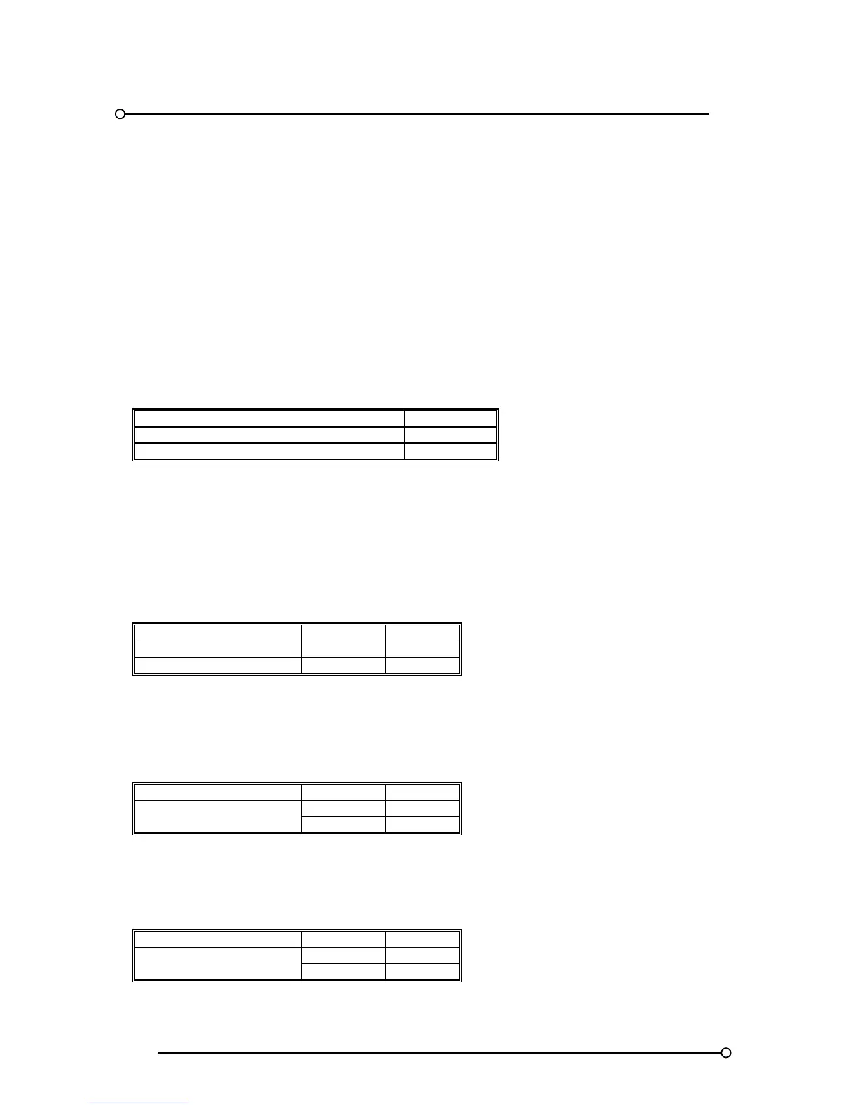
FUNCTION SW1-8
Outputs suitable for driving lamps ON
Outputs suitable for driving LED’s OFF
11.3 Tropicalisation (Option TRO)
In harsh environmental conditions all of the associated cards are sprayed with a conformal coating
and sealed relays are used as required.
11.4 Individual Channel Repeat Relays (Option RLY)
As an option each dual channel alarm card within the annunciator can be supplied with two relays to
allow a repeat signal from each channel to be sent to third party devices as required. The non alarm
coil state of each relay can be set to be either:-
FEATURE FUNCTION SETTING
Normally energised F2 OFF
Normally de-energised F2 ON
The operation mode of each relay can be selected to be either:-
Input Follower
The individual relay will activate when an alarm occurs and automatically return to normal when the
signal input returns to the normal state.
FEATURE FUNCTION SETTING
Input follower
F18 OFF
F19 ON
Logic Follower
The individual relay will activate when an alarm occurs and only return to normal when the signal
input has returned to the normal state and the logic has reset, this may require the operator to press
the associated pushbuttons to reset the alarm depending on the sequence selected.
FEATURE FUNCTION SETTING
Logic follower
F18 ON
F19 OFF