RTK Series 725 Annunciator
69
23. Alarm Card Address Settings
Dual Channel Alarm Card Address And Output Drive Type Settings
Before each card is placed within the annunciator a unique address No. has to be set using the
switches located on DIL switch SW1, which allows the programming module to communicate and
pass programming instructions to and from the associated alarm channels. When replacing an alarm
card the switches on DIL Switch SW1 must be set to match the card that is being removed.
SW1-* FUNCTION ON OFF
SW1-1 Set address Bit 1 1 0
SW1-2 Set address Bit 2 1 0
SW1-3 Set address Bit 3 1 0
SW1-4 Set address Bit 4 1 0
SW1-5 Set address Bit 5 1 0
SW1-6 Set address Bit 6 1 0
SW1-7 Set address Bit 7 1 0
23.1 Set Output Drive To Operate With Lamps or LED
SW1-8
Conventional filament lamps SW1-8 ON
Fit & forget LED assemblies SW1-8 OFF
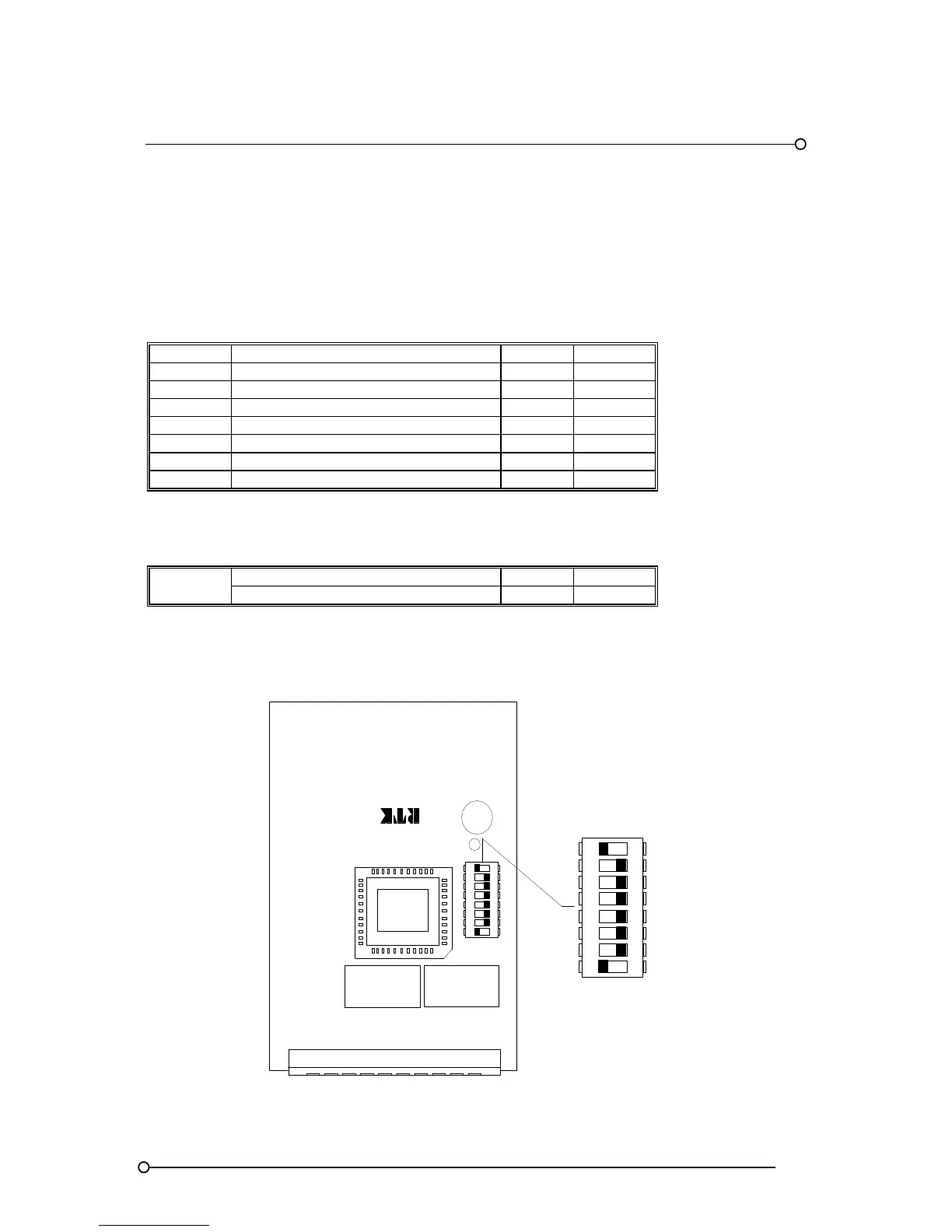
Alarm Card DIL Switch SW1 Location
SW1 DIL SWITCH
OFFON
OFFON
A4506-*
RL2
RL1
ALARM CARD
1
2 3 4 5 6 7 8
1
2 3 4 5 6 7 8

 Loading...
