RTK Series 725 Annunciator
45
12. Large Window Alarm Module Wiring
Series 725 units supplied with large windows provide one alarm per cell. In order to maximise the
use of the standard two channel alarm card all odd cells within the annunciator, (1,3,5,7, etc), are
equipped with alarm cards and all even cells, (2,4,6,8, etc), are left unequipped. Channel 1 of the
alarm card is routed to the lamps or LED’s in the normal way and channel 2 is routed by the display
motherboard to the lamps or LED’s located in the cell directly below.
12.1 Standard Unit Without Repeat Relay Facility
Each cell is equipped with a type A2 back plate and a dual channel alarm card model no
CB5674POP1, which is suitable for 2 signal inputs. The alarm card is located in the upper card slot
12.2 Optional Unit With Repeat Relay Facility
Each cell is equipped with a type AR2 back plate and dual channel alarm card model no
CB5674POP2, which is suitable for 2 signal inputs and provides 2 relay outputs each having one set
of changeover contacts. The alarm card is located in the upper card slot
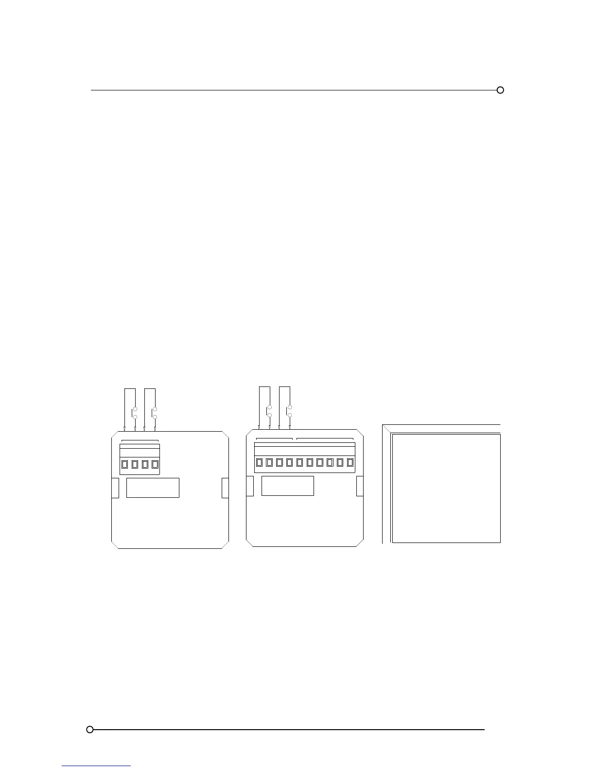
Wiring Details For A2 And AR2 Modules In Large Window Versions
WIRING FOR UNITS
WITH LARGE WINDOWS
WITH REPEAT RELAYS
CH*
INPUT
INPUT
WIRING FOR UNITS
WITH LARGE WINDOWS
WITHOUT REPEAT RELAYS
CH*
1
C
A2
C1
INPUT 1
INPUT 1
RELAY OUTPUTS
AR2
NCC2 NO R1
INPUT 2
DRIVES ALARM
IN CELL BELOW
R2NONC
2 C
1
INPUT 2
DRIVES ALARM
IN CELL BELOW
FRONT VIEW
WINDOW LAYOUT