RTK Series 725 Annunciator
16
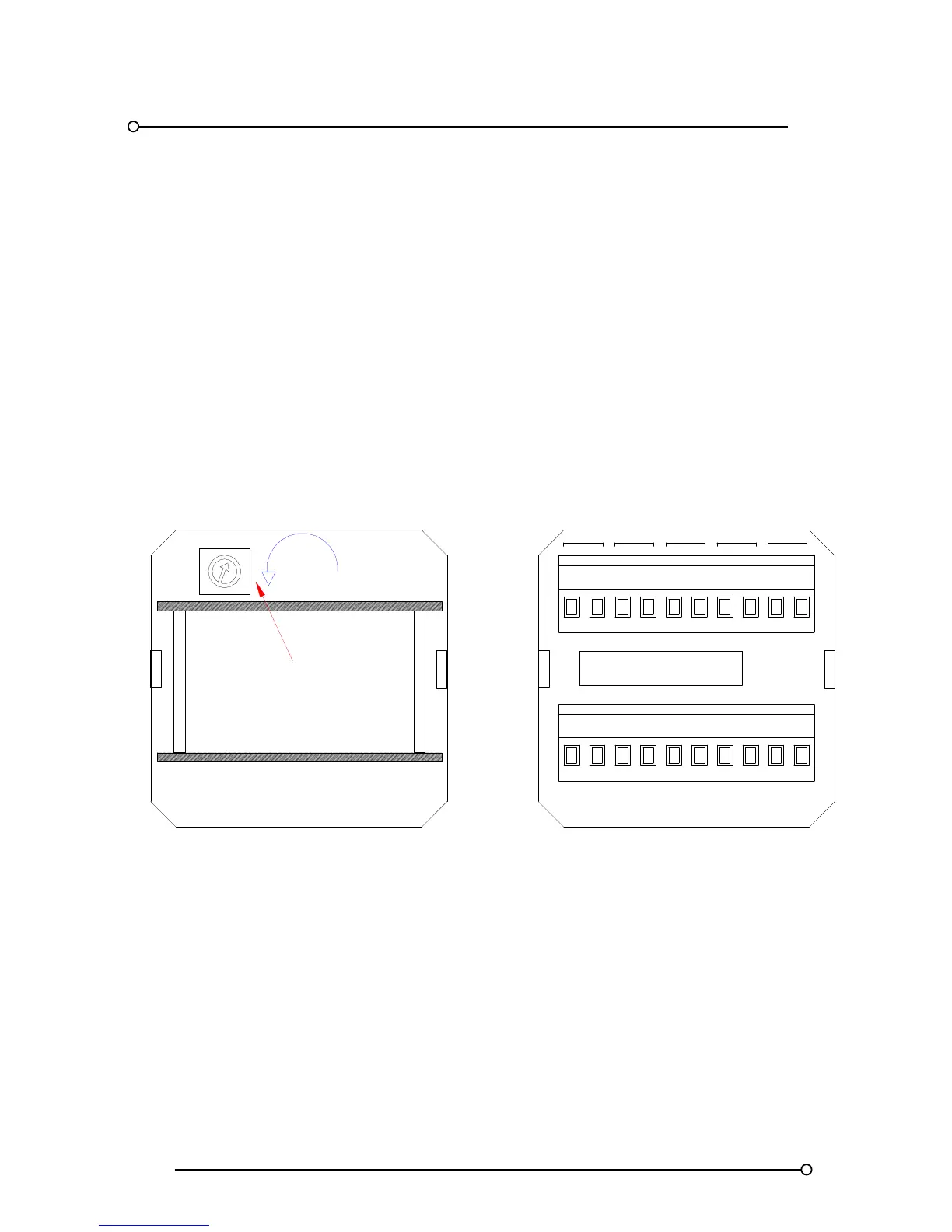
3.14a Horn adjustment on Remote Pushbutton / Programming Modules
On P725 Systems supplied with Remote Pushbutton / Programme Modules the horn adjustment
potentiometer is located in an alternative position to that shown above. The potentiometer can only
be accessed from the rear of the Pushbutton cell using the following procedure.
1. Remove Power From the annunciator
2. Remove the two green terminal blocks which provide customer terminations on the rear of
the pushbutton cell.
3. Remove the plastic protection cover on the rear of the pushbutton cell
4. The potentiometer is now accessed on the inside face of the pushbutton cell and can be
adjusted as required
Once adjustment has been made the plastic cover and customer terminal blocks can be re-fitted and
the power can be applied to check the volume level.
HNB
SUPPLY 24VDC
OV OVC
+V
HNA
ST
+VC
T A R
SPR
FRM
GPBGPA
MULT
REAR VIEW OF PUSHBUTTON CELL WITH
TERMINALS AND COVER REMOVED
REAR VIEW OF COVER / TERMINALS
Increase
HORN VOLUME
ADJUSTMENT