RTK Series 725 Annunciator
13
3.12 Sleep Mode
Sleep mode is typically used in sub station applications where the visual and audible outputs are
disabled during unmanned periods to reduce the drain on the associated station batteries.
Whilst in sleep mode the logic of the annunciator will continue to react in the normal way including
the operation of common alarm relays, watchdog relay and optional signal duplicating relays, only the
drive signals to the lamp and audible drives are disabled.
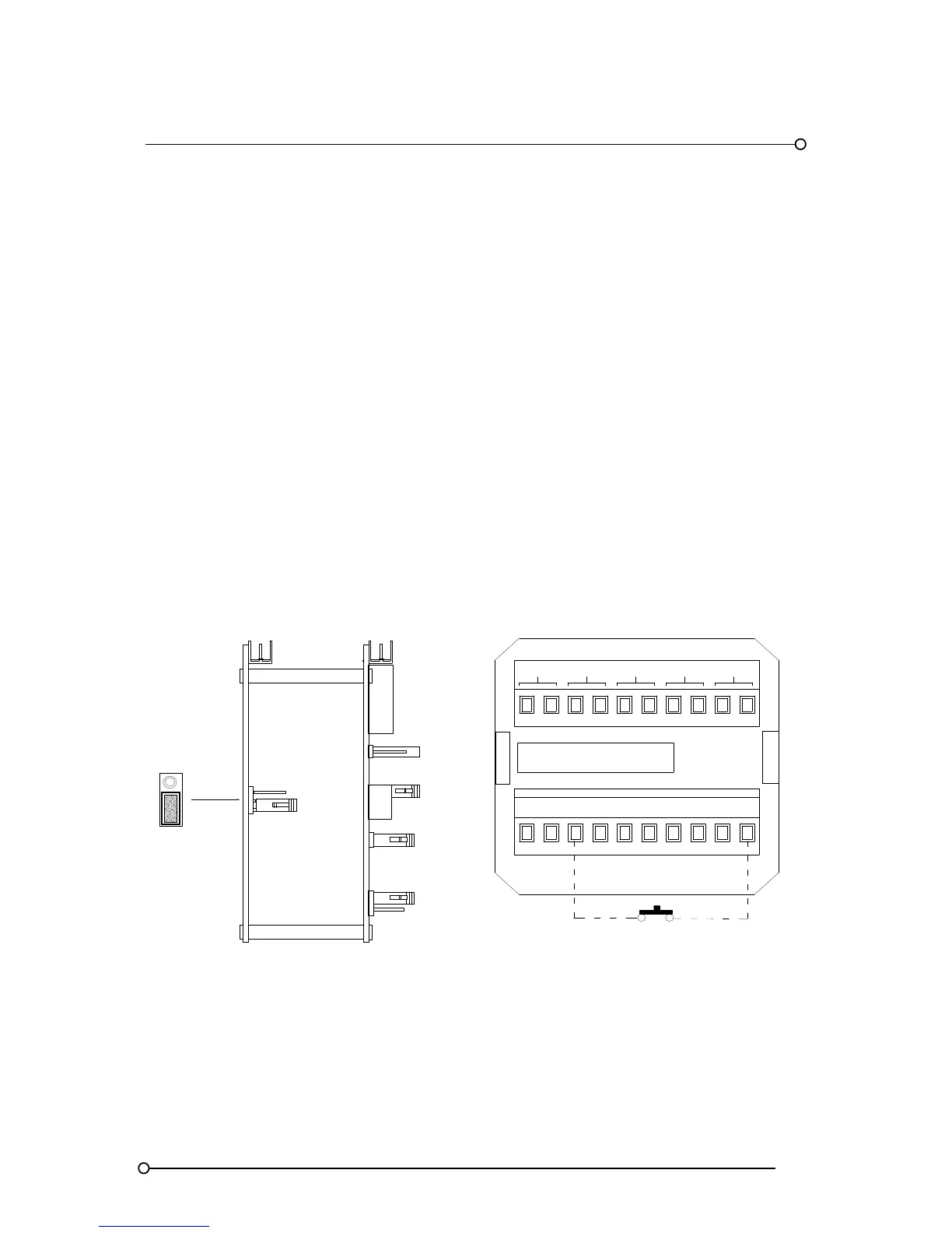
Before sleep mode can be enabled a jumper link must be pre-set on the SPR card located inside the
pushbutton / programming cell. To gain access to the SPR card first remove the back-plate on the
SPR module and then remove the associated circuit card assembly using a flat blade screw driver to
gently lever the assembly out using the white nylon pillar. Once the card has been removed locate
the 3 pin header marked FR and SP which is located on the lower of the two cards and check that
the 2 way shorting bar is in the SP position as shown below. Once the jumper has been placed into
the correct position and the card assembly placed back into the annunciator the unit can be set to
sleep mode using a remote mounting normally open maintained switch with one side of the switch
connected to +V (+24VDC) and the other side of the switch connected to terminal FR located on the
rear of the pushbutton / programming cell. Whilst the switch is maintained in the closed position the
unit will remain in sleep mode.
Note: - All normal pushbutton functions are inhibited during sleep mode to ensure that the operator
can view any alarms that occur as soon as the unit is returned to its normal operational state.
Sleep Mode Jumper Location
FR
SP
SUPPLY 24VDC
SPR
FR
OV OVC +V +VC T A R ST M
MULT
GPBGPA
HNBHNA
Side View
Assy Pt No
CB4642POP1
Sleep Mode Switch