RTK Series 725 Annunciator
82
27. Serial Communication Port
This section describes the process of reading from and writing data to a P725 slave annunciator, and
also the different types of data interchange possible. The tables below show the standard message
formats for data interchange, for both ASCII and RTU protocols.
ASCII tables. Each character represents 7 bit binary data in ASCII format with the
exception of the characters in brackets, which should be considered as one
character.
X represents a character with more than one possible value.
All characters are framed with 1start bit, 1parity bit and 1 stop bit.
RTU tables. Each character represents 8 bit binary data in hexadecimal format.
Y represents a character with more than one possible value.
All characters are framed with 1 start bit, 1parity bit and 1 stop bit.
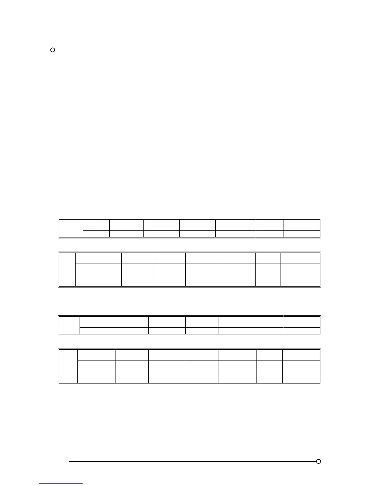
Read Request – Master
ASCII
START ADDRESS FUNCTION
REGISTER
ADDRESS
NO OF
REGISTERS
ERROR
CHECK
STOP
: XX 03 XXXX 0001 XX [LF] [CR]
RTU
START ADDRESS FUNCTION
REGISTER
ADDRESS
NO OF
REGISTERS
ERROR
CHECK
STOP
ELAPSED TIME 3
½
CHARACTERS
MIN
Y 3 YY 01 YY
ELAPSED TIME
3 ½
CHARACTERS
MIN
Read Response - P725 Slave
ASCII
START ADDRESS FUNCTION
BYTE
COUNT
DATA
ERROR
CHECK
STOP