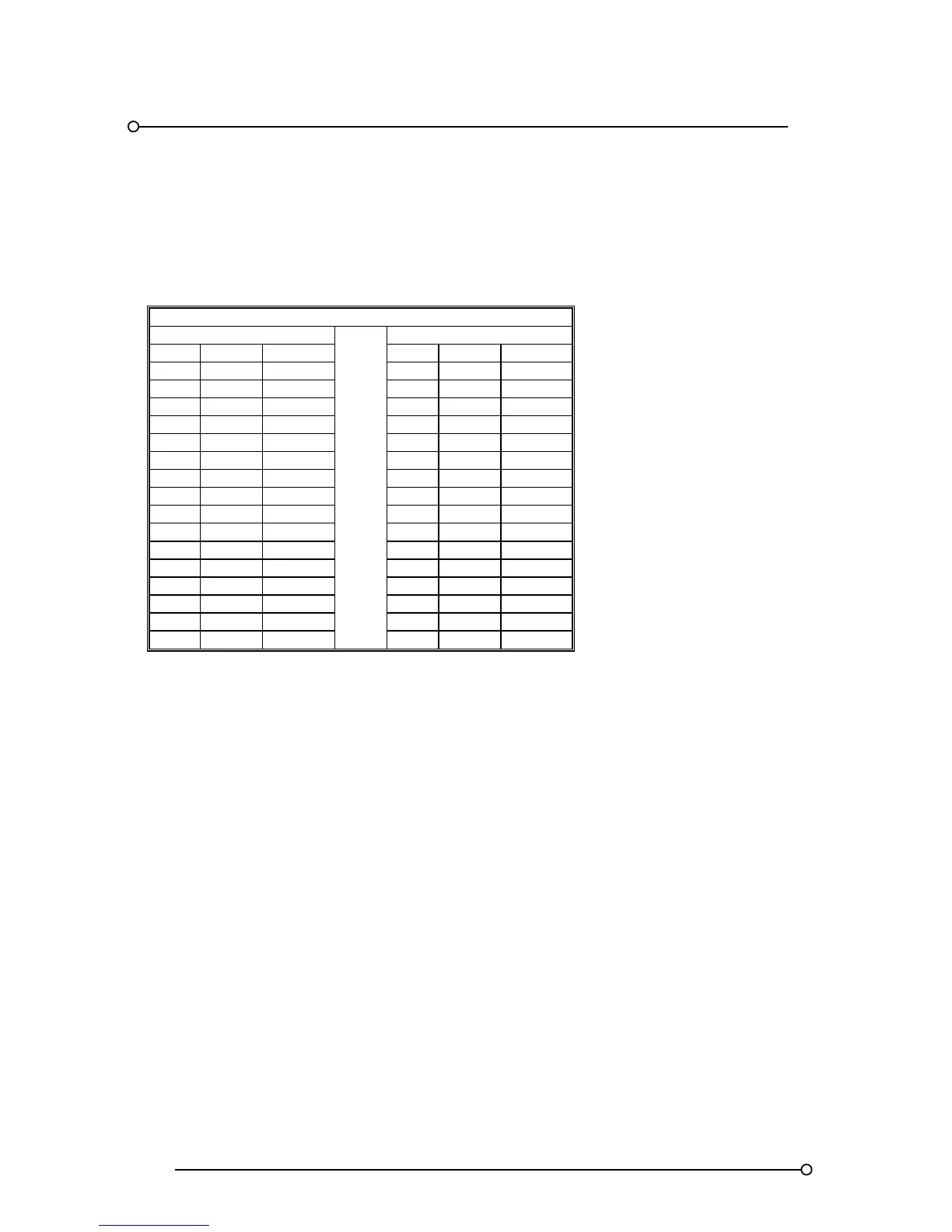
Cut-Out
1 84 74 1 84 74
2 144 134 2 144 134
3 204 194 3 204 194
4 264 254 4 264 254
5 324 314 5 324 314
6 384 374 6 384 374
7 444 434 7 444 434
8 504 494 8 504 494
9 564 554 9 564 554
10 624 614 10 624 614
11 684 674 11 684 674
12 744 734 12 744 734
13 804 794 13 804 794
14 864 854 14 864 854
15 924 914 15 924 914
16 984 974 16 984 974
Please note:- The cut out tolerance should be with ±2mm. Annunciator depth is 145mm
Caution
The above table indicates the dimensions based on the number of cells high X cells wide this should
not be confused with the number of alarm windows high and wide which can vary depending on
required window size. i.e. There would be :- 1 x Large window per cell, 2 x Medium windows per cell,
or 4 x Small windows per cell.
7.2 System Capacity
The maximum number of alarms available within a single annunciator is dependent on the maximum
number of cards the system can address. This is fixed at 128 two channel cards, making the
maximum system size for all window sizes 256 channels.
In applications where a number of separate annunciators are linked together to form a common
system the max capacity for the whole system will remain at 256 alarms.