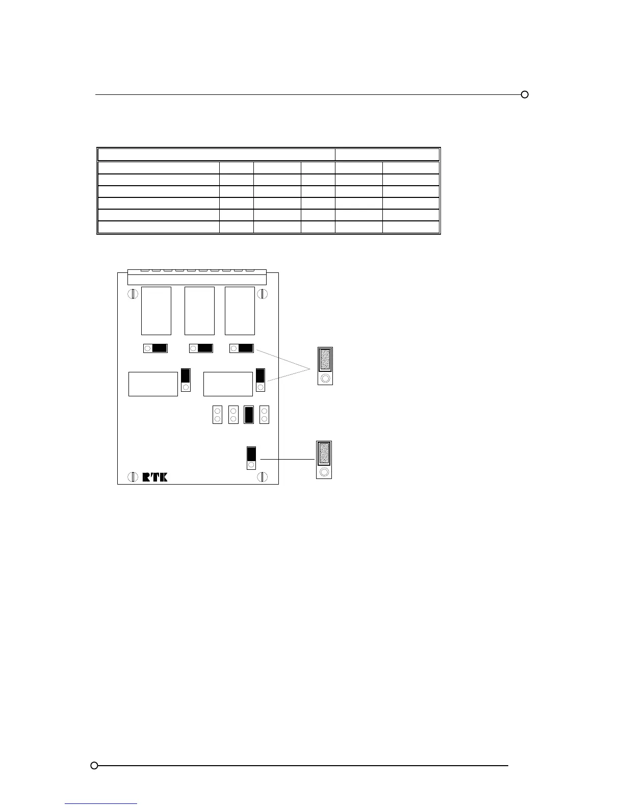
Critical horn relay HNA RL1 LK1 N/O N/C
Non critical horn relay HNB RL2 LK2 N/O N/C
Critical group relay GPA RL3 LK3 N/O N/C
Non-critical group relay GPB RL4 LK4 N/O N/C
Multifunctional relay MUL RL5 LK5 N/O N/C
Pt No CB4642POP1
N/C
RL2 - HNB
HORN RELAY
RL3
GPA
GROUP
RELAY
RL5
MULT.
FUNCT.
RELAY
LK5
RL4 - GPB
GROUP RELAY
N/O
LK4
N/O
N/C
N/C
N/O
LK3
1ST
COMM'S
STD
LK10
RBHGP WD
COMM'S
STD
CONTACT SET
NORMALLY CLOSED
NORMALLY OPEN
RL1
HNA
HORN
RELAY
LK6
LK2
LK8
LK7
LK9
N/O
LK1
N/C
N/O
N/C
N/O
N/C
5.2 Critical Horn Relay - HNA
When an alarm occurs the horn relay will change state and remain in the alarm condition until the
mute or ack pushbutton has been pressed. Each channel can be set to operate the critical horn relay
as required. Please note:- Channels set to operate the critical horn relay will also operate the integral
audible alarm.
5.3 Non-Critical Horn Relay - HNB
When an alarm occurs the relay will change state and remain in the alarm condition until the mute or
ack pushbutton has been pressed. Each channel can be set to operate the non- critical horn relay as
required. Please note:- Channels set to operate the non-critical horn relay will not operate the integral
audible alarm.