RTK Series 725 Annunciator
50
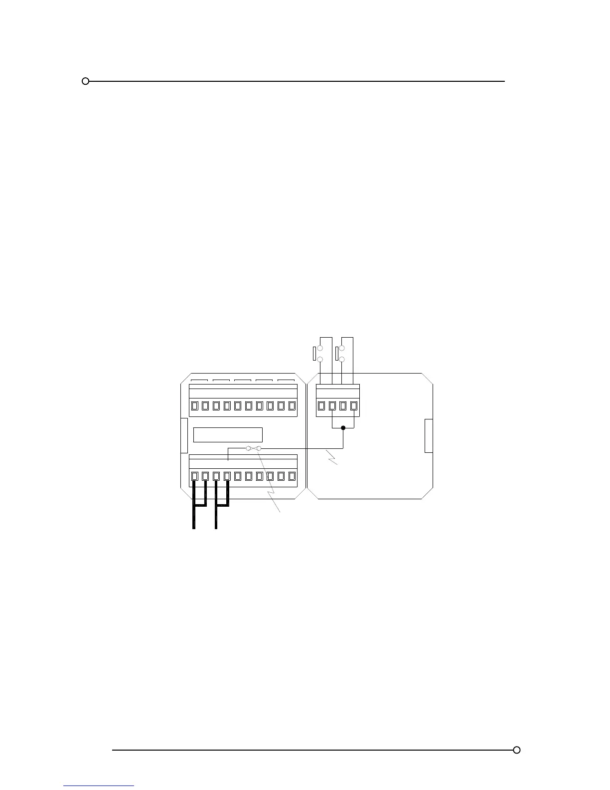
16. Signal Supply Voltage Options
16.1 Standard Systems With Combined Logic And Signal Supply.
In standard systems the 24VDC logic supply, OV and +V is cross-linked to the signal supply input
terminals, OVC and +VC to provide the voltage required to power the input contacts. Systems are
supplied with a factory fitted jumper between these terminals.
The signal supply input terminal +VC is used to internally link 24VDC Via a fuse to all of the common
terminals within the annunciator marked “C” ready for connection to customer signal contacts
Systems Using A Single 24VDC For Logic And Signal Supply
FR
MULT
SUPPLY 24VDC
+V
HNB
OV OVC
HNA
T
+VC
A STR M
SPR
GPA GPB
24VDC LOGIC
SUPPLY
1
C
2
C
INTERNAL DISTRIBUTION OF
SIGNAL SUPPLY VOLTAGE
INTERNAL
1A SIGNAL
SUPPLY FUSE
TYPICAL SIGNAL INPUTS
Earthing
All 725 Series Alarm Annunciators are fitted with a separate earth stud, which is located on the metal
frame extrusion.
Warning:- To ensure the final installation meets all relevant safety standards and EMC directives this
earth must be connected