RTK Series 725 Annunciator
57
18. Power Distribution
Power Distribution On Large Annunciator Units
Systems greater than 32 cells are equipped with a minimum of one SI/O supply card to allow the
user to distribute the logic supply load and avoid excessive current being passed through the
motherboard. The first 32 cells in the annunciator are powered from the SPR module in the normal
way. Each SI/O card is designed to power a maximum of 16 cells in larger applications multiple SI/O
cards will therefore be present. With systems up to 48 cells the logic supply is factory wired between
the SPR and SI/O cells however on systems over 48 cells it is necessary to power the SPR and SI/O
cells using separate feed wires due to the higher currents required.
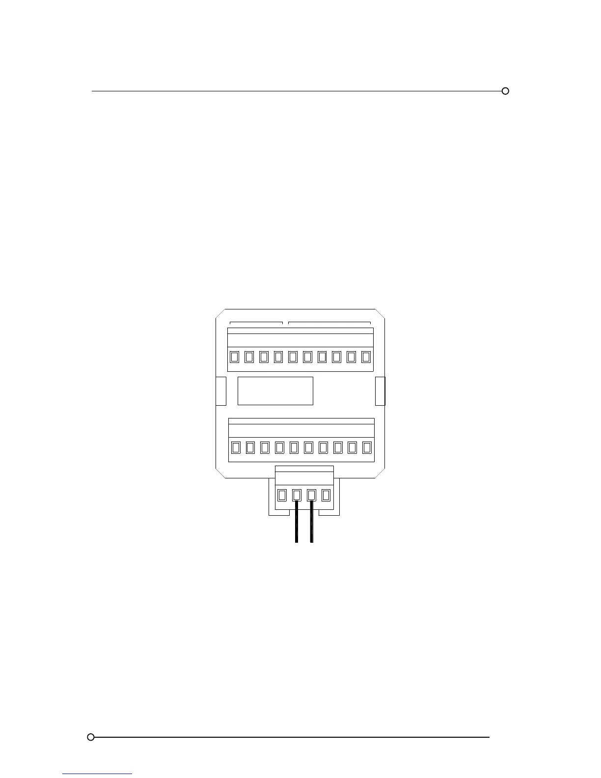
Typical SPR Module Wiring On AR4 Type Alarm Module
RELAY OUTPUTS
INPUT
CH*
NCC
4
C3
C
1
C
2
NC
NO
R4
NO R3 NC
NO
R1
NC R2NO
OVOV +V+V
24VDC LOGIC SUPPLY
SPR
Please Note:-
SI/O cards do not occupy the space of active alarm cards therefore units can be supplied fully
populated.