RTK Series 725 Annunciator
18
4. Inputs
4.1 Optically Coupled Inputs
All alarm inputs are provided with fully isolated inputs using optical couplers and a transient filter is
built into the input circuitry so that low voltage interference will be ignored.
4.2 Standard Input Configuration
The standard Series 725 annunciator can be set to operate from volt free signal contacts that are
either normally open or normally closed.
Setting function F1 to the off state conditions the input to accept a normally open contact.
Setting function F1 to the on state conditions the input to accept a normally closed contact.
Please note:- when using the Customer adjustable response time options AD* on P725 Annunciator
supplied after March 2009 Function F1 should always be set to “OFF” and switch SW2 should be
used to set the Input to normally open or normally closed as described in Section 24 of this manual
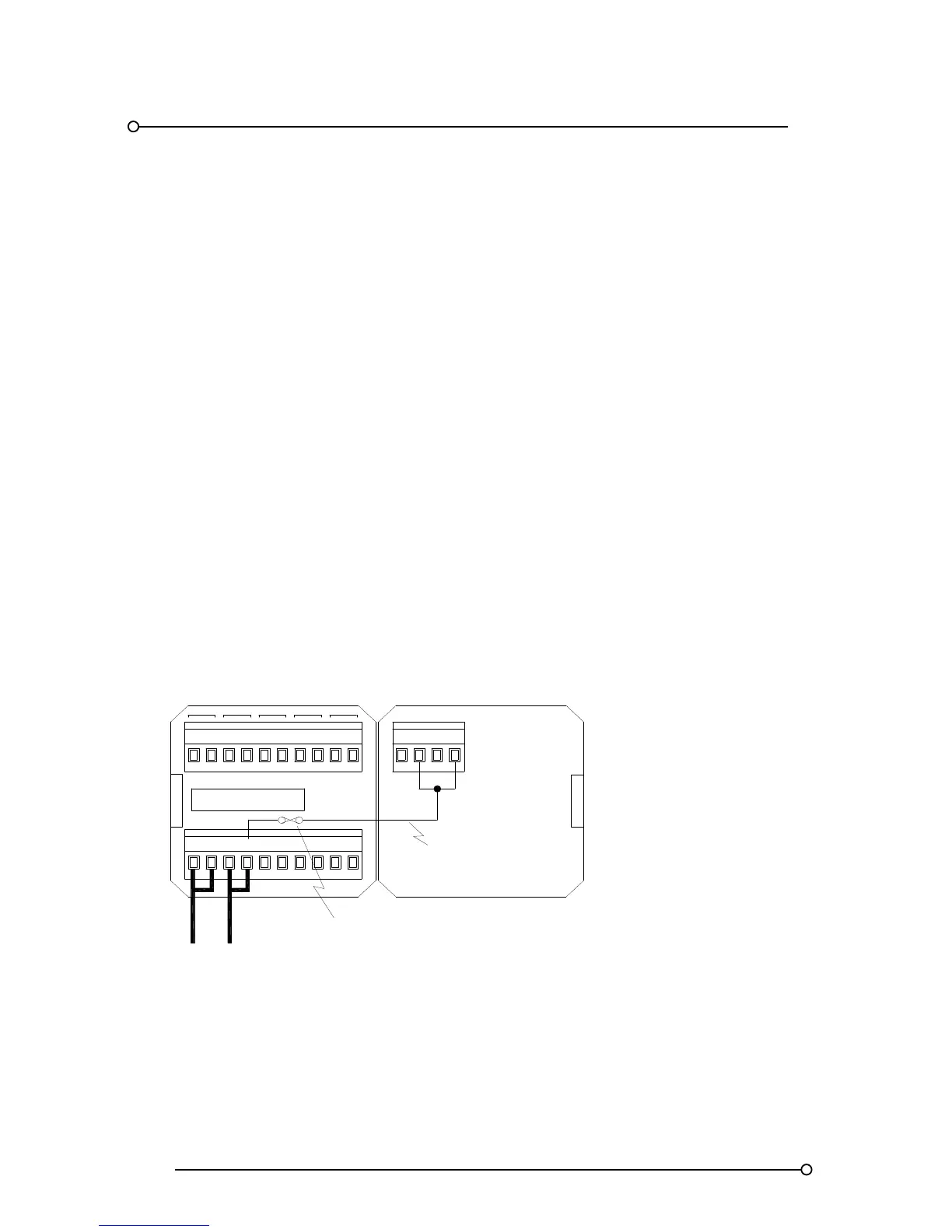
4.3 Signal Supply Voltage
On standard units an internally fused 24vdc signal supply (+VC), derived from the 24VDC logic
supply (+V), is distributed to all of the common terminals marked “C” which are located to the right of
each signal input terminal as typically shown below.
Typical Signal Supply Voltage Distribution
Logic supply
Internally distributed
signal supply voltage
Internal
1A signal
supply fuse
OVCOV
+V
+VC
RT A
ST
M FR
SPR
MULT
SUPPLY 24VDC
HNA HNB
GPBGPA C1 C2
+24V
OV