RTK Series 725 Annunciator
41
Display Follower
The individual relay will activate when an alarm occurs and faithfully mimic the state of the output
drive to the associated lamp (flashing, on or off)
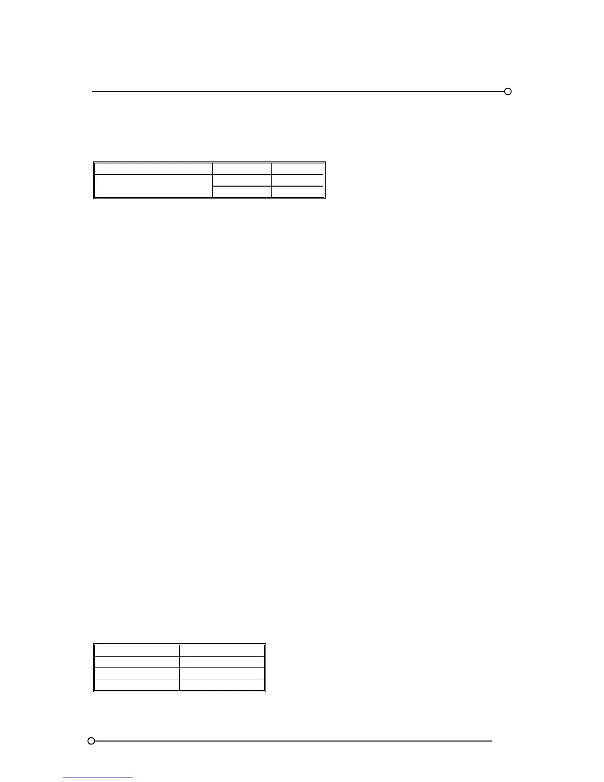
FEATURE FUNCTION SETTING
Display follower
F18 ON
F19 ON
11.5 Individual Channel Dual Repeat Relays (Option RL2)
In applications that require two repeat relay outputs for each channel a dual channel alarm card
complete with repeat relays and a dual channel relay card are required. The dual channel relay card l
provides the additional set of volt-free changeover contacts. Please note:- As this feature requires
additional card slots it is only available on systems using medium or large windows.
11.6 Customer Specified Response Time (Option CRT**)
The response time for standard units is factory set at 25ms. If alternative response times are
required, option CRT is used to specify a fixed response time, between 1ms and 2 seconds.
11.7 Adjustable Response Time (Option AD*)
If specified at the time of order each channel can be supplied with a trim pot that allows the user to
adjust the response time between two set points as required.
AD1 = 5ms to 50ms, AD2 = 25ms to 2 seconds or AD3 = 5ms to 5 seconds
Please note: When setting activation delays it is important to note that the same delay will apply to
the return to normal state, for example:- If a channel is set for 5 Seconds delay the input contact
must be in the abnormal state for a minimum of 5 Seconds before the alarm activates. Once the input
contact has returned to normal the channel will not recognise the return to normal state for a
minimum of 5 Seconds and therefore the channel cannot be reset until this delay has elapsed.
On P725 annunciators supplied after March 2009 each channel is equipped with a switch, (SW2),
which allows the user to select
Return to normal state should have the same delay as the alarm activation or
Return to normal state as soon as the input returns to normal.
When using AD* options the user must use SW2 to set the normally open or normally closed input
state as detailed later in the manual. Function F1 should be set to OFF when using SW2 as
described in Section 24 of this manual.
11.8 Disable Integral Horn (Option DHN)
All units are supplied with an integral piezo audible as standard, which follows the critical audible
group (HNA). If remote audibles only connected to the integral horn relays are required the unit can
be supplied with the horn disabled.
11.9 Higher Field Contact Voltages (Option FCxx)
Standard 725 annunciators are able to accept powered signal inputs @ 24VAC/DC and as an option
the unit can be supplied suitable for direct connection to powered inputs
OPTION CODE VOLTAGE
FC048 48VAC / DC
FC125 125VAC / DC
FC250 250VAC / DC