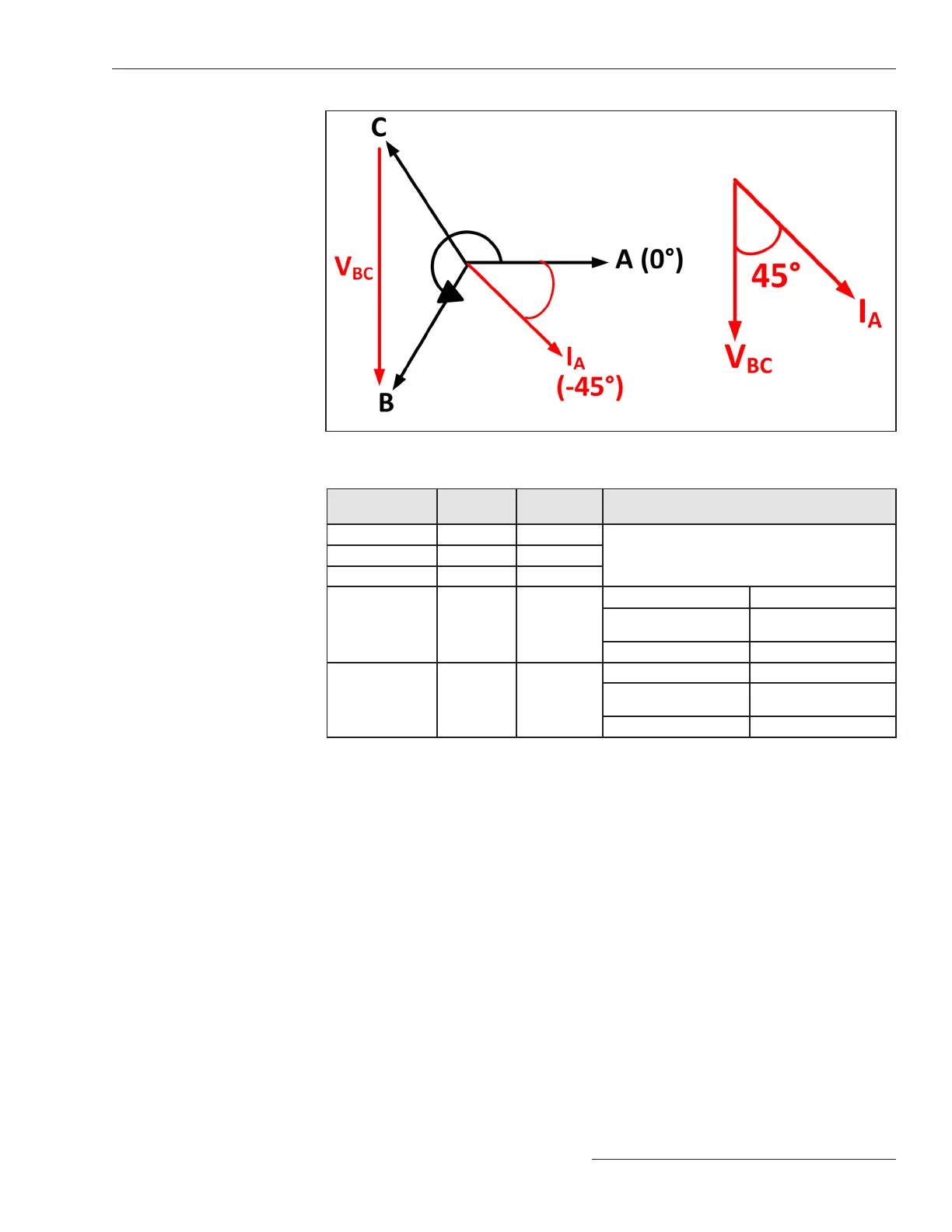
Figure 10. Phase-A direction example for a 1-2-3 rotation.
Table 1. System Grounding Method for Terminal-Y Fault
Directional
Measurement
Operating
Current
Reference
Voltage
Terminal Y
Max Torque Angle
Phase-A IA VB - VC
-45º (1-2-3 rotation)
+135º (1-3-2 rotation)
Phase-B IB VC - VA
Phase-C IC VA - VB
Ground 3I0 3V0
-135º Ungrounded
+135º
Uni-Grounded
Resonant
+135º All others
Zero Sequence
(SEF filtered
3V0>10%)
3I0 3V0
+90º Ungrounded
0º
Uni-Grounded
Resonant
-135º All others
Referring to Table 1 and Figure 10 and using the Terminal-Y Phase-A directional
measurement as an example, V
BC
is the reference voltage and I
A
is the operating current.
The Terminal-Y Phase-A MTA is -45° for a 1-2-3 (A-B-C) rotation.
Therefore,
∠MTA = ∠V
BC
- ∠I
A
, and
∠I
A
= ∠V
BC
- ∠MTA
Substituting -45° from Table 1 for ∠MTA, maximum torque is achieved when
∠I
A
= ∠(V
BC
+ 45°),
or the Terminal-Y Phase-A directional MTA occurs when IA leads VBC by 45° for a
1-2-3 rotation.
Referring to Table 1 and Figure 11 on page 24, if the corresponding operating current
leads or lags its reference voltage by ±90° from the respective maximum torque angle
(MTA), the fault is determined to be on Terminal-Y. Otherwise, the fault is determined
to be on Terminal-X, or is unknown.
S&C Instruction Sheet 766-530 23
General Setup
 Loading...


