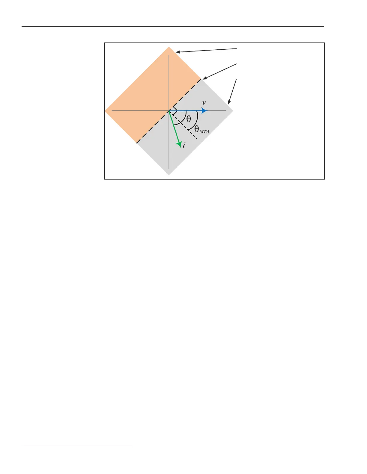
Figure 11. Directional boundary diagram based on maximum torque angles.
If the current phasor falls here,
torque direction is X
If the current phasor falls on line,
torque direction is undetermined
If the current phasor falls here,
torque direction is Y
When a fault initiates and the phase-to-ground voltage is <16% of the nominal system
phase-to-ground voltage, pre-fault phase-to-ground memory voltage is used to measure
torque angles when required. In the event the pre-fault phase-to-ground memory voltage
is <16% of the nominal system phase-to-ground voltage, protection elements may operate
non-directionally. When protection elements operate non-directionally, the Fault Direc-
tion Indeterminate flag is set and logged.
System Frequency
Select the system frequency, either the 60 Hz or 50 Hz option.
System Phase-to-Phase Voltage
Enter the value of the system phase-to-phase voltage in kV. (Range: 4.00-40.00; Step:
0.01 kV; Default: 12.47)
Voltage Reporting
Select from the drop-down list: the Phase to Ground or Phase to Phase option. This
setting applies to values reported on the Operation screen, the Metering screen, and the
DNP voltage Analog Points.
Voltage Reporting Base
Select from the drop-down list: the 120 Vac (default), 240 Vac, %, or kV option. This
setting only applies to the values reported on the Operation and Metering screens.
24 S&C Instruction Sheet 766-530
General Setup

 Loading...


