Chapter 2 Installation Electrical Installation
18 Series PM172 Powermeters
Terminals
+RX
16
RS-422/RS-485
POWER SUPPLY
-RX-TX +TX
VN
9 6
1413 15
11
5
V
3
8
Handle Only at
COM.1
1
Workstations
Static-Safe
COM.2
Static-Sensitive
Devices
ATTENTION
17
N/-
L/+
12
10
9
2
1
10-16VDC
18-36VDC
36-72VDC
2V
5
(24)
(48)
(12)
O
S/N
S
N
LOW DC
CT.
I
1A
T
DIGITAL INPUTS
90-264VAC
50/60Hz
85-290VDC
POWER SUPPLY
V
1
2
10W
O
P
ANALOG OUTPUTS
2018 19
12
23
+
21 22
+
262524
3
7
6
2
4
1
-
3
RELAYS
+
1
2928
27
21
ANALOG INPUTS
ANALOG IN/OUT :
+1mA
-
0-20mA
4-20mA
0-1mA
+
+
-
-
--
CALIBRATED AT :
25 Hz
60 Hz
50 Hz
400 Hz
COM.1 :
RS-232/422/485 STANDARD
ETHERNET
MODEM
PROFIBUS
690V
OPT.U
STANDARD
CT.
5A
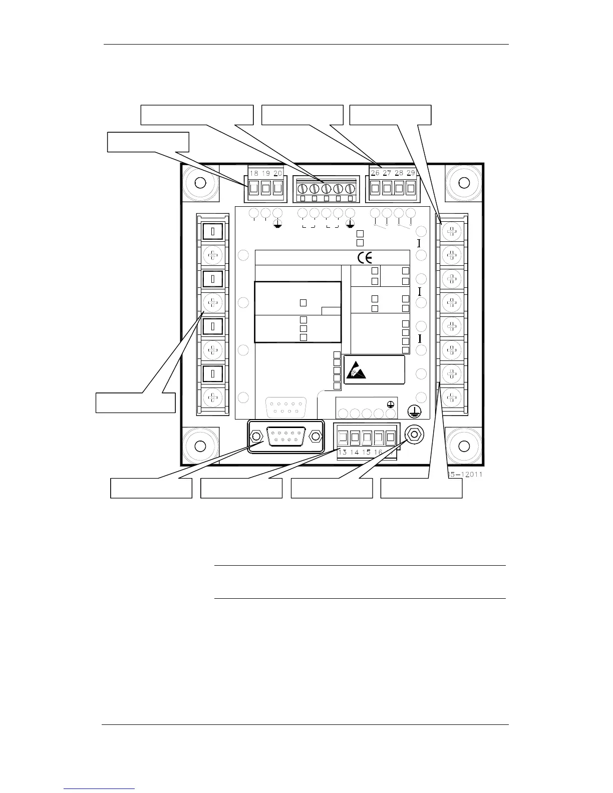
Figure 2-16 Terminals - Rear View
Power Source Connection
Before connecting your meter to the power source, check the label on the
back of the device to ensure that it is equipped with the appropriate power
supply.
The power source can be dedicated-fused, or from a monitored voltage if it is
within the instrument power supply range.
AC power supply: connect the line wire to terminal 12 and the neutral wire to
terminal 10.
DC power supply: connect the positive wire to terminal 12 and the negative
wire to terminal 10.
Chassis Ground