Chassis Ground Connection
Connect the chassis ground of the device to the switchgear earth ground
using a dedicated wire greater than 2 mm
2
/14 AWG.
Wiring Diagrams
For AC input ratings, see “Technical Specifications” in Appendix A.
The following wiring configurations are available in the meter:
Wiring Configuration
(See Basic Device Settings in Chapter 3)
Setup Code Figure
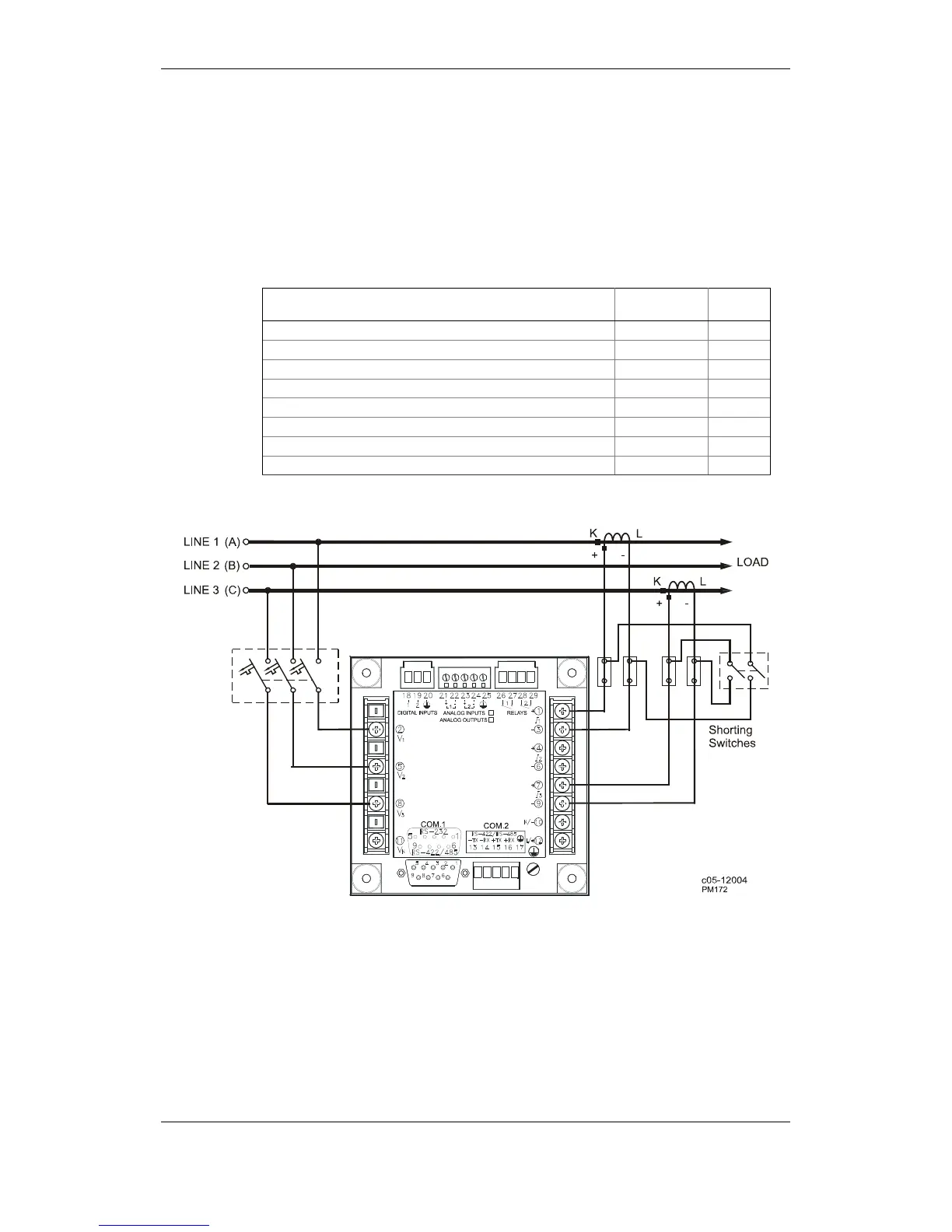
3-wire 2-element Direct connection using 2 CTs 3dir2 2-17
4-wire Wye 3-element direct connection using 3 CTs 4Ln3 or 4LL3 2-18
4-wire Wye 3-element connection using 3 PTs, 3 CTs 4Ln3 or 4LL3 2-19
3-wire 2-element Open Delta connection using 2 PTs, 2 CTs 3OP2 2-20
4-wire Wye 2½ -element connection using 2 PTs, 3 CTs 3Ln3 or 3LL3 2-21
3-wire 2½ -element Open Delta connection using 2 PTs, 3 CTs 3OP3 2-22
4-wire 3-element Delta direct connection using 3 CTs 4Ln3 or 4LL3 2-23
3-wire 2½-element Broken Delta connection using 2 PTs, 3 CTs 3bLn3 or 3bLL3 2-24
Figure 2-17 3-Wire 2-Element Direct Connection Using 2 CTs.
Wiring Mode = 3dir2