Scaling Non-directional Analog Inputs
For non-directional analog inputs with the 0-1mA, 0-20mA and 4-20mA
current options, provide both zero and full engineering scales. Each of the
scales operates independently.
Scaling ±1mA Analog Inputs
For directional ±1mA analog inputs, you should provide only the engineering
scale for the +1 mA input current. The engineering scale for the 0 mA input
current is always equal to zero. The device does not allow you to access this
setting. Whenever the direction of the input current is changed to negative,
the device automatically uses your full engineering scale settings for +1 mA
with a negative sign.
Scaling Analog Inputs for 0-2 mA and ±2 mA
The input scales for 0-1 mA and ±1 mA analog inputs are always
programmed for 0 mA and +1 mA regardless of the desired input range. If
you want to use the entire input range of 2 mA or ±2 mA, set the analog input
scales in your device as follows:
0-2 mA: set the 1 mA scale to 1/2 of the required full scale
output for uni-directional parameters, and set the 0 mA
scale to the negative full scale and the 1 mA scale to zero
for bi-directional parameters.
±2 mA: set the 1 mA scale to 1/2 of the required full-scale
output for both uni-directional and bi-directional
parameters.
For example, to convert voltage readings from the analog transducer that
transmits them in the range of 0 to 2 mA to the range 0 to 120V, set the full
range for the +1 mA analog input to 60V; then the 2 mA reading is scaled to
120V.
Programming Analog Outputs
The meter can be ordered with two optional analog outputs with options for
0-1mA, ±1mA, 0-20mA or 4-20mA output currents.
The 0-1mA and ±1mA current outputs provide a 100% overload, and actually
output currents up to 2 mA and ±2mA whenever the output value exceeds
the engineering scale set for the 1 mA or ±1mA.
To configure the Analog Outputs in your device, select General Setup from
the Meter Setup menu, and then click on the Analog Outputs tab. If you are
programming your device online, analog outputs are designated as not
available if they are not present in the device.
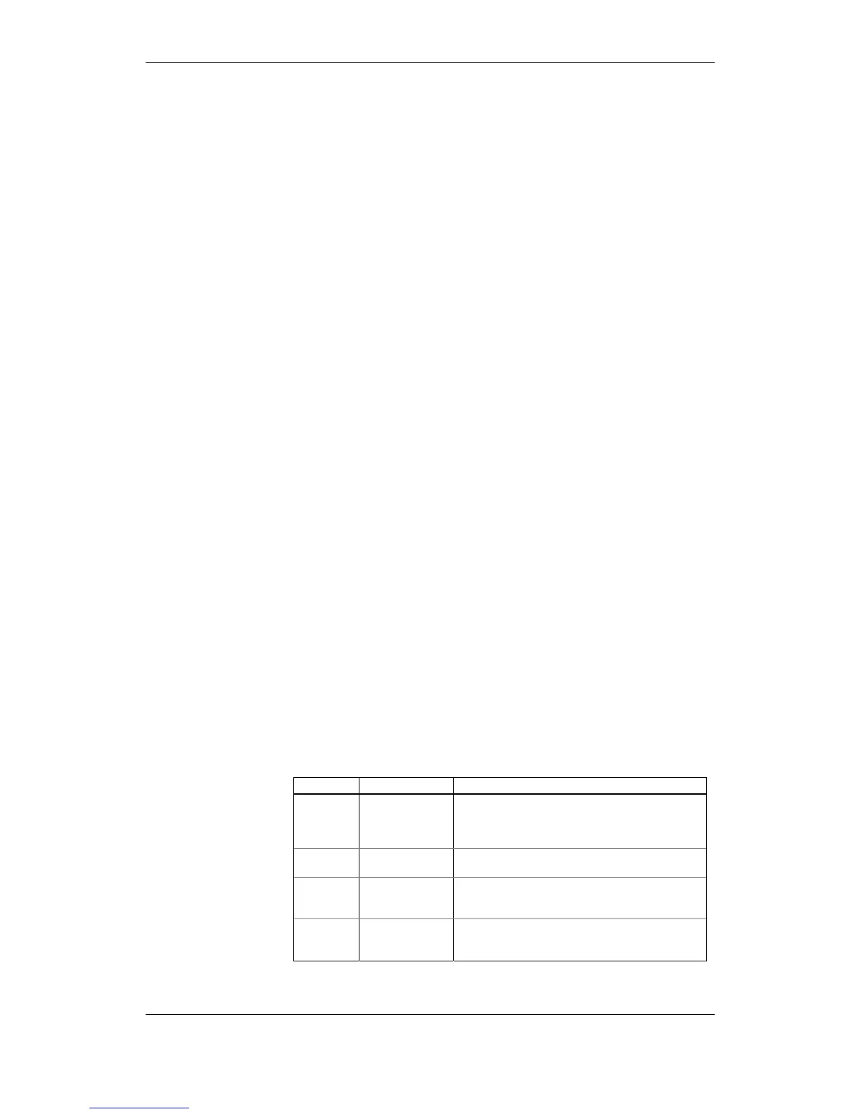
The available analog output options are described in the following table.
Option Range Description
AO type
0-1mA
±1mA
0-20mA
4-20mA
The analog output type. When connected to the
meter, shows the actual AO type read from the
device. When working off-line, select the analog
output option corresponding to your meter.
Output
parameter
See Appendix B
Selects the measured parameter to be transmitted
through the analog output channel.
Zero scale
Defines the low engineering scale (in primary units)
for the analog output corresponding to a lowest
(zero) output current (0 or 4 mA)
Full scale
Defines the high engineering scale (in primary units)
for the analog output corresponding to a highest
output current (1 or 20 mA)