Chapter 3 Display Operations Menu Operations
48 Series PM172 Powermeters
2. Use the UP and DOWN arrow buttons to select the
desired value.
3. Press ENTER to confirm the new parameter setting, or
press ESC to discard changes.
4. You are returned to the middle window to select and
configure another parameter, or confirm the settings and
exit the menu.
To store your new settings:
1. When the middle window is highlighted, press the ENTER
button.
2. You are returned to the upper window to select another
relay or exit the menu.
To exit the menu, press ESC.
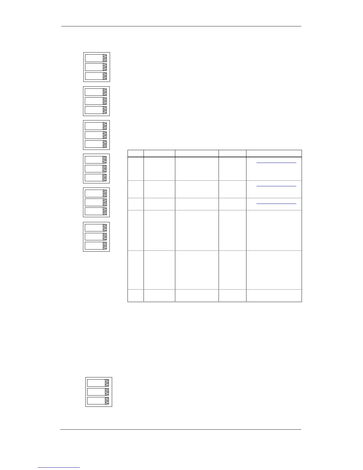
The following table lists available relay options.
Label Parameter Options Default Description
tYPE Operation
mode
UnLt = Unlatched
Ltch = Latched
PLS.A = Pulse
PLS.C = KYZ pulse
UnLt See Using Relay Outputs
in Chapter 4
Polr Polarity nor = Normal (N.O.)
InS = Inverting
(N.C.)
nor See Using Relay Outputs
in Chapter 4
rtnt Retentive
mode
diS = Disabled
En = Enabled
diS See Using Relay Outputs
in Chapter 4
PuLS Pulse width 20-1000 ms 100 ms The actual pulse width is
a multiple of the 1-cycle
time rounded to the
nearest bigger value.
The pause time between
pulses is equal to the
pulse width.
Src Pulse source nonE
Ac.Ei = kWh IMP
Ac.EE = kWh EXP
rE.Ei = kvarh IMP
rE.EE = kvarh EXP
rE.Et = kvarh TOT
AP.Et = kVAh
NONE Links a pulse relay to the
internal energy pulse
source. The relay must be
set into either pulse, or
KYZ mode.
Unit Pulse rate,
kWh/Pulse
0.1-1000.0 1.0
kWh/Pulse
Defines the pulse weight
in kWh units per pulse
Control Setpoints Setup
The PM172 provides 16 control setpoints with programmable operate and
release delays. Each setpoint evaluates a logical expression with up to four
arguments using OR/AND logic. Whenever an expression is evaluated as
“true”, the setpoint performs up to four concurrent actions that send a
command to the output relays, increment or decrement a counter, or trigger a
recorder. For more information on setpoints operation, see “Using Control
Setpoints” in Chapter 4.
This menu configures setpoints through the front display. To enter the menu,
select the “SEtP” entry from the Main menu, and press the ENTER button.
The menu uses three entries:
1. The upper window indicates a setpoint number.
2. The middle window selects a setup parameter to view or
change.
3. The lower window displays the parameter value.
SEtP
ESC
rEL.1
PulS
tYPE
rEL.1
nor
Pol