Chapter 2 Installation Communications Connections
30 Series PM172 Powermeters
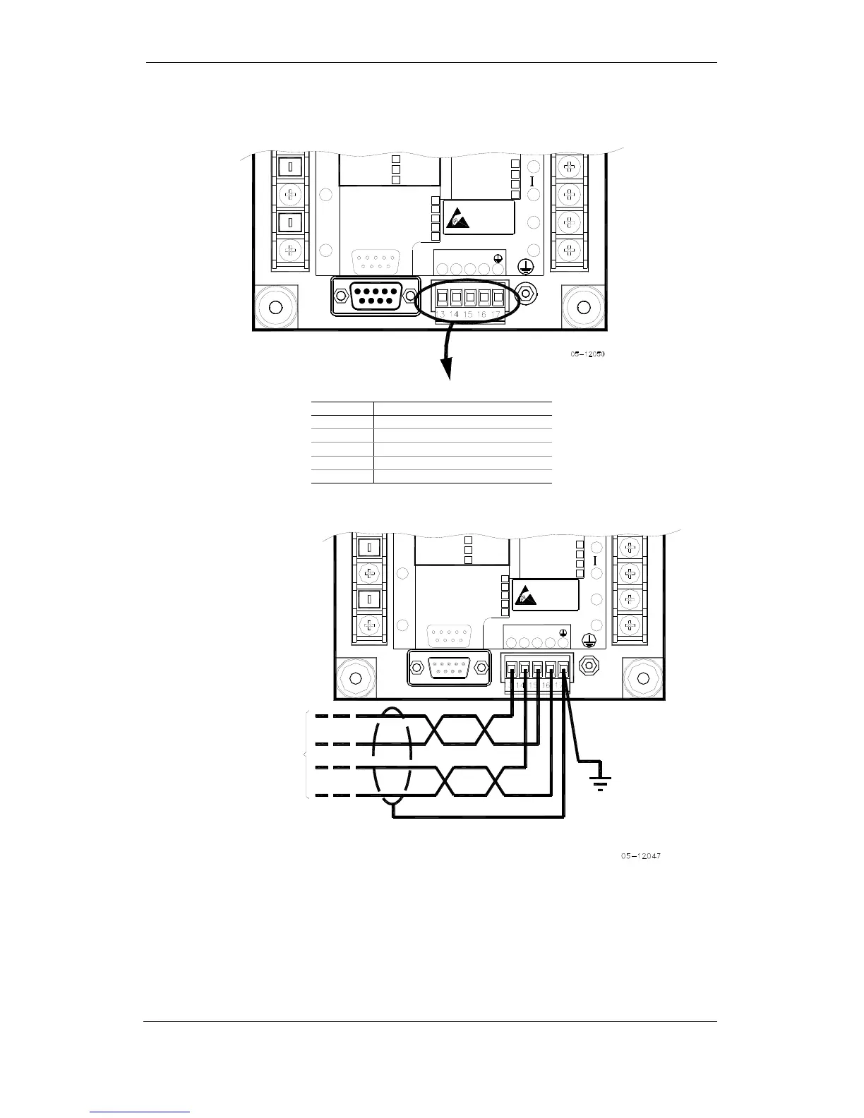
COM2 RS-422/485 Connection
-4-20mA
9
8
COM.1 :
ATTENTION
Devices
Static-Sensitive
Static-Safe
Workstations
Handle Only at
POWER SUPPLY
RS-422/RS-485
16
+RX
COM.2COM.1
11
V
1513 14
69
N
1
5
-TX +TX-RX
V
MODEM
PROFIBUS
ETHERNET
RS-232/422/485 STANDARD
3
17
12
L/+
N/-
10
ANALOG IN/OUT :
0-1mA
0-20mA
V
-
+1mA
LOW DC
N
(24) 18-36VDC
(48) 36-72VDC
S
2
(12) 10-16VDC
+
7
3
9
6
5
1
Connector removable, captured-wire, 5 terminals:
Terminal Signal
13 -TxD
14 -RxD
15 +TxD
16 +RxD
17 Ground
-4-20mA
9
8
COM.1 :
ATTENTION
Devices
Static-Sensitive
Static-Safe
Workstations
Handle Only at
POWER SUPPLY
RS-422/RS-485
16
+RX
COM.2COM.1
11
V
1513 14
69
N
1
5
-TX +TX-RX
V
MODEM
PROFIBUS
ETHERNET
RS-232/422/485 STANDARD
3
17
12
L/+
N/-
10
ANALOG IN/OUT :
0-1mA
0-20mA
V
-
+1mA
LOW DC
N
(24) 18-36VDC
(48) 36-72VDC
S
2
(12) 10-16VDC
+
7
3
4 WIRE CONNECTION
RS-485/422 COMMUNICATION PORT
TO COMMUNICATION
SYSTEM
_
+
+
_
Rx
Tx
Figure 2-33 COM2: RS-422/485 4 Wire Connection