Figure 2-11 Panel cutout dimensions
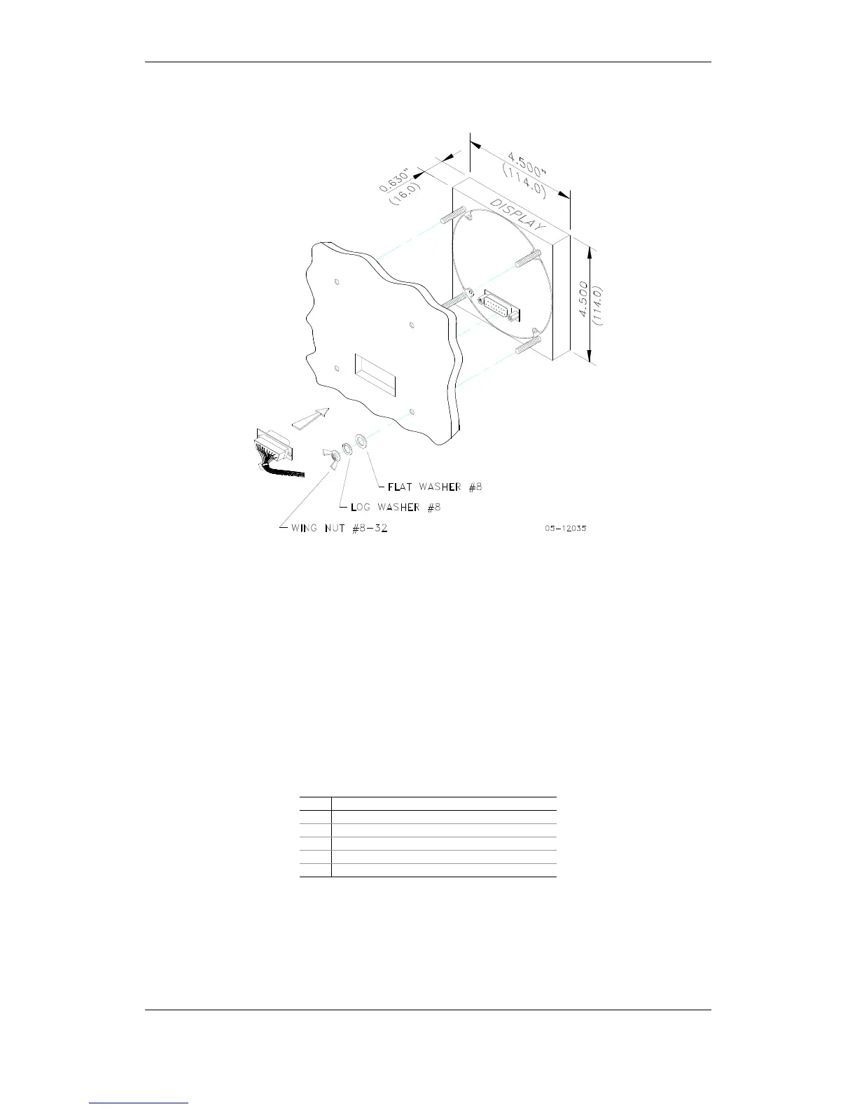
Figure 2-12 Display mounting
Electrical Connection
The remote display is connected to the meter via a 3-wire or 5-wire
communication cable provided with two 15-pin D-type connectors.
At distances of up to 3 m, the display can receive power through the
communication cable directly from the meter. Connect pins 1 and 8 on both
sides as shown in Figure 2-13.
At distances above 3 m, power should be provided from a separate 12V DC
power source (a 12V AC/DC adapter can be used). Connect the positive
wire to pin 1 and the negative wire to pin 8 as shown in Figure 2-14.
Pin Signal
1 +12V
5 RS-485 + (plus)
7 RS-485 – (minus)
8 GND
15 Chassis ground