Chapter 2 Installation Remote Display Installation
16 Series PM172 Powermeters
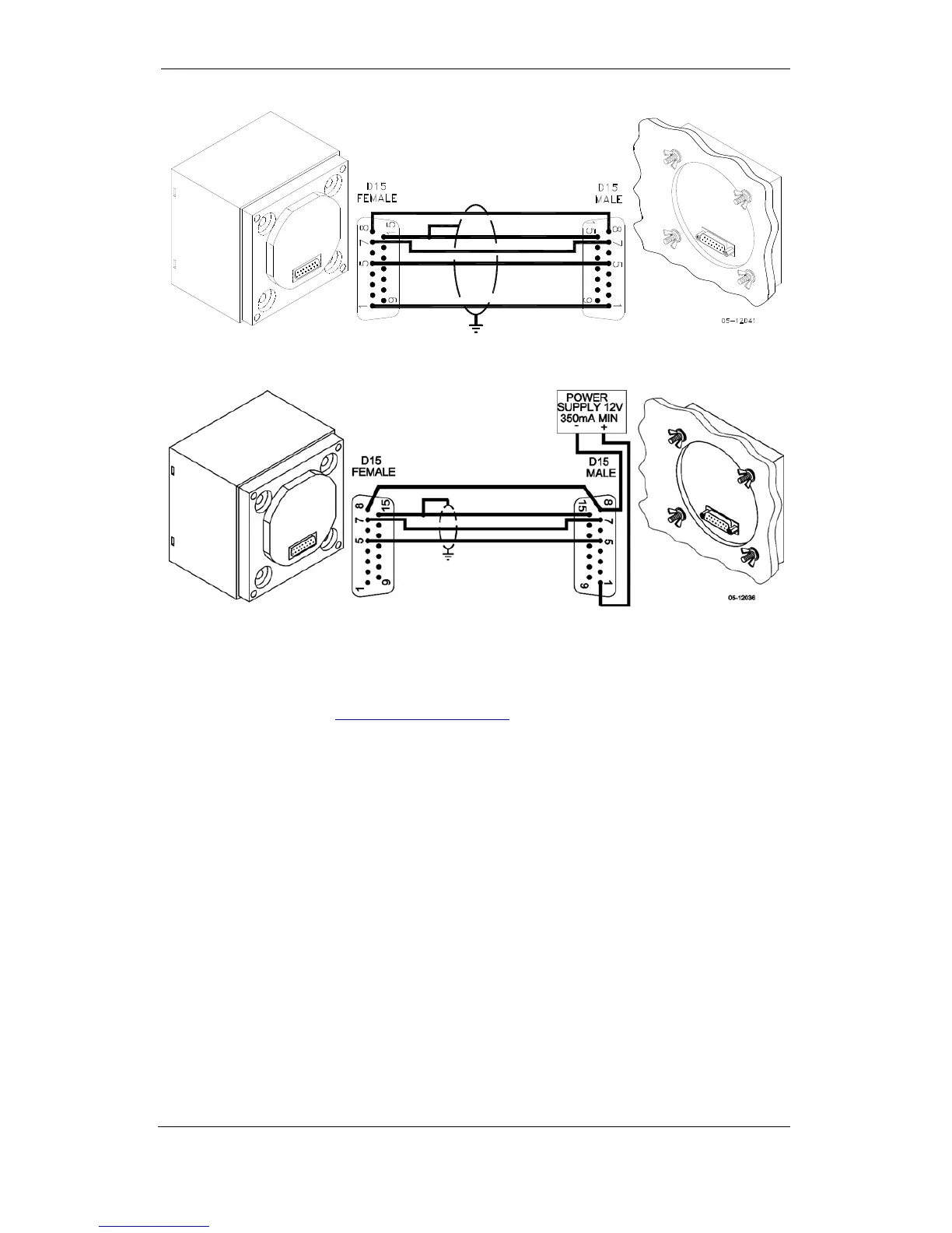
Figure 2-13 Self-powered remote display connection
Figure 2-14 Remote display powered from a 12V DC power source
If required, the remote display may be connected to one of the regular meter
ports COM1 or COM2 via a three-wire RS-485 communication cable using a
separate 12V DC power source as shown in Figure 2-14. See
Communications Connections for connector pin-outs and connection
diagrams. The meter port settings must be as follows: Modbus RTU protocol,
RS-485 interface, 19200 baud, 8-bits/no parity.