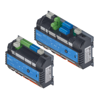
Hardware manual PCD7.LRxx-PG5 room controller │ Document 27-653; version ENG07 │ 2019-03-21
Saia-Burgess Controls AG
Manual PCD7.LRxx-PG5
Table of contents
0-2
0
3.1.5 Removal from mounting rails ..................................................................... 3-5
3.1.6 Wall mounting ............................................................................................ 3-6
3.1.7 Removal from the wall ............................................................................... 3-6
3.2 Electrical data ............................................................................................ 3-7
3.2.1 PCD7.LRL2-P5, -.LRL4-P5 and -.LRS4-P5 (230 VAC models) ................. 3-7
3.2.2 PCD7.LRL5-P5 and PCD7.LRS5-P5 (24 VAC) ......................................... 3-7
3.3 Power supply and earthing concept ........................................................... 3-8
3.3.1 Devices with a 230 VAC supply ................................................................. 3-8
3.3.2 Devices with a 24 VAC supply ................................................................... 3-9
......... 3-10
3.3.4 Earthing concept ....................................................................................... 3-11
3.4 CPU properties .......................................................................................... 3-12
3.5 General technical details ........................................................................... 3-13
3.6 Firmware/Operating system ....................................................................... 3-14
3.7 System memory structure .......................................................................... 3-15
3.8 System resources ...................................................................................... 3-16
3.8.1 User program in block structure ................................................................. 3-16
3.8.2 Data types/value ranges ............................................................................ 3-17
3.8.3 Resource elements .................................................................................... 3-17
3.8.4 RTC/internal hardware clock ...................................................................... 3-17
3.9 LED/operating states ................................................................................. 3-18
3.10 RUN/HALT key ........................................................................................... 3-19
3.10.1 Multiple uses for the RUN/HALT key ......................................................... 3-19
3.10.2 Restart the controller with RUN/HALT button ............................................ 3-20
3.11 Watchdog (software) .................................................................................. 3-21
4 Inputs and outputs
4.1 Connection overview and functions ........................................................... 4-2
4.2.1 Use as digital inputs ................................................................................... 4-8
4.2.1.1 Digital input 24 VDC with source operation ............................................... 4-8
4.2.1.2 Digital input 24 VDC with sink operation .................................................... 4-8
4.2.1.3 Digital input as dry contact ......................................................................... 4-8
.......................................... 4-9
4.2.1.5 Programming digital inputs ........................................................................ 4-10
4.2.2 Use as analogue inputs ............................................................................. 4-11
4.2.2.1 Analogue input with 0…10V ...................................................................... 4-11
4.2.2.2 Analogue input as resistance measurement .............................................. 4-11
4.2.2.3 Analogue input as temp. measurement ..................................................... 4-11
........................................................ 4-12
4.2.2.5 Programming analogue inputs ................................................................... 4-14
.............................. 4-14
4.2.2.7 Status registers .......................................................................................... 4-15
4.3 ROx/TOx - Digital outputs .......................................................................... 4-16

 Loading...