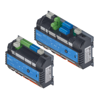
Hardware manual PCD7.LRxx-PG5 room controller │ Document 27-653; version ENG07 │ 2019-03-21
Saia-Burgess Controls AG
Manual PCD7.LRxx-PG5
Table of contents
0-3
0
4.3.1 ROx - Relay outputs .................................................................................. 4-16
4.3.2 TOx - Triac outputs .................................................................................... 4-18
4.3.3 Current limitations for the terminal «24 VAC Out» ..................................... 4-18
4.3.4 Connection examples for Triac Outputs ..................................................... 4-19
4.3.4.1 Triac outputs 24VAC external power supply .............................................. 4-19
4.3.4.2 Triac outputs 24VAC internal powered ...................................................... 4-20
4.3.4.3 Triac outputs 230VAC external power supply ............................................ 4-21
4.4 AOx - Analogue outputs ............................................................................. 4-22
4.5 Connection examples ............................................................................... 4-23
5 Communication interfaces
5.1 PGU (Micro-USB port) programming interface .......................................... 5-2
5.2 Using the SBC S-Bus protocol ................................................................... 5-3
5.3 RS-485 interfaces (ports 0 + 1) in general ................................................. 5-4
5.3.1 Schematic diagram of a PCD7.LRxx-P5 room controller in
an RS-485 bus with terminating resistors .................................................. 5-5
5.3.2 Bus cable for serial S-Net (S-Bus/RS-485) ................................................ 5-6
5.3.3 Requirements for the S-Bus (RS-485) shielding ........................................ 5-7
5.3.4 RS-485 interface port0 ............................................................................... 5-7
5.3.5 RS-485 interface port 1 .............................................................................. 5-8
5.3.5.1 Sample system architecture for I/O extension ........................................... 5-8
5.3.5.2 Limitations for I/O extension with E-Line modules ..................................... 5-8
5.3.5.3 Recommendations for use with lighting or blind control ............................ 5-11
5.3.5.4 DALI with E-Line (PCD1.F2611-C15 module) ............................................ 5-13
5.4 Modbus on PCD7.LRxx-P5 RS-485 interfaces .......................................... 5-14
5.4.1 Limitations .................................................................................................. 5-14
5.4.2 Addressing ................................................................................................. 5-15
5.4.3 Media Mapping .......................................................................................... 5-17
5.5 Sylk bus ..................................................................................................... 5-23
5.5.1 Key information about the bus ................................................................... 5-23
5.5.2 Recommendations regarding the PCD7.LR-TR40x/TR42x wall modules . 5-24
5.5.3 Devices and Programming/FBoxes ........................................................... 5-24
6 Conguration
................................................... 6-2
6.1.1 Requirement for operation ......................................................................... 6-2
6.1.2 General ...................................................................................................... 6-2
................................................................... 6-4
................................................................ 6-4
............................................................... 6-4
6.2.3 Media mapping view .................................................................................. 6-5
6.2.4 Digital/analogue universal inputs ............................................................... 6-6
6.2.5 Relay outputs ............................................................................................. 6-8
6.2.6 Triac outputs .............................................................................................. 6-9
6.2.7 Analogue outputs ....................................................................................... 6-10

 Loading...