Hardware manual PCD7.LRxx-PG5 room controller │ Document 27-653; version ENG07 │ 2019-03-21
Saia-Burgess Controls AG
Universal inputs
Inputs/outputs (I/O)
4-6
4
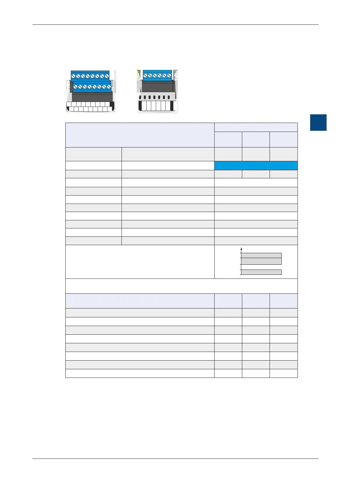
4.2 UIx - Universal inputs
PCD7LRLx-P5 PCD7LRSx-P5
RO3 IN3 RN RN IN0 RO0 IN1 RO1 IN2 RO2
RUN/HALT
Sylk Bus
RS485 / Port 1
UI0…
0
-
10 V
GND
Dig. NTC
V
TN T~ TO0TNTO1 TO2 TN TO3
RS485 / Port 0
C1+/D A +
D B -
GND
C1-
AO0…
GND
0
-
10V
V
Power Supply
24 VAC
Out
---
230 V
24 VAC
---
USB
T2 R2 T1 R1
!
1
L
2
N
3
24V~
4
24V0
5
24V~
6
24V0
7
TN
8
T~
9
TO0
10
TN
11
TO1
12
TO2
13
TN
14
TO3
15
RC3
16
RO3
17
IN3
18
RN
19
RN
20
IN0
21
RO0
22
IN1
23
RO1
24
IN2
25
RO2
/DA+
26
DB-
27
GND
28
24V~
29
/DA+
62
DB-
63
GND
64
WM1
30
WM2
31
AO0
32
AO1
34
AO2
36
AO3
38
AO4
40
AO5
42
GND
33
24V~
35
GND
37
24V~
39
GND
41
24V~
43
24V~
44
GND
46
UI1
48
UI2
50
GND
52
UI5
54
LED
45
UI0
47
GND
49
UI3
51
UI4
53
GND
55
UI6
56
GND
58
UI9
60
UI7
57
UI8
59
GND
61
1 2 5 6 7 8 9 10 11 12 13 14 16 17 18 19 20 21 22 23 24 25
33 35 37 39 41 43
47 49 53 55 57 59 6151
26 27 28 29 30 31 32 34 36 38 40 42
46 48 52 54 56 58 6050
AO0…
GND
0-10V
V
UI0…
0-10 V
GND
Dig. NTC
V
RS485 / Port 0
/D A +
D B -
RO3 IN3 RN RN IN0 RO0 IN1 RO1 IN2 RO2
TN T~ TO0 TN TO1
RUN/HALT
Power Supply
---
230 V In
24 VAC In
24 VAC Out
Sylk Bus
RS485 / Port 1
USB
T1 R1 T0 R0
!
1
L
2
N
3
24V~
4
24V0
5
TN
6
T~
7
TO0
8
TN
9
TO1
10
RO3
11
IN3
12
RN
13
RN
14
IN0
15
RO0
16
IN1
17
RO1
18
IN2
19
RO2
AO0
26
24V~
27
GND
28
AO1
29
AO2
30
24V~
31
UI0
34
GND
35
UI1
36
/DA+
40
DB-
41
GND
42
UI2
37
GND
38
UI3
39
GND
32
AO3
33
WM1
20
WM2
21
24V~
22
/DA+
23
DB-
24
GND
25
1 2
3 4 5 6 7 8 9 10 11 12 13 14 15 16 17 18 19
40
41
4226 27 28 29 30 31 32
33
34
35
36
37
38
39
20 21 22
23 24 25
Technical information PCD7._ _ _ _-P5
LRL2
LRL4
LRL5
LRSx
Number of
universal inputs
Electrically connected 6 10 4
Terminal block colour -
Blue
Terminal label - UI0…5 UI0…9 UI0…3
Terminal type Plug-in screw-type terminals up to 2.5 mm
2
Yes
Galvanic isolation From supply and other I/Os No
Input voltage Typically V DC (15...30 V DC) Yes
Input current Typically 0.1 mA with 24 V DC Yes
Input delay 12 ms Yes
Switching level Low: 0…5 V, high: 15…30 V DC Yes
Overvoltage protection - No
LED I/O optical digital display No
1
0
30 V
DC
24 V
DC
15 V
DC
5 V
DC
usage.
Usage as … Type 7* Type 7*
Type 8
Type 7*
Digital input 24 V DC with source operation 6 10 4
Digital input 24 V DC with sink operation 6 6 4
Digital input as dry contact 6 6 4
Analogue input with 0…10V 6 10 4
Analogue input as resistance measurement 0…2,5 kOhm --- 4 ---
Analogue input as resistance measurement 0…10 kOhm --- 4 ---
Analogue input as resistance measurement 0…100 kOhm 6 6 4
Analogue input as temp. measurement PT/NI1000 L&S --- 4 ---
* Description of Types 7 and 8 see next page
The universal inputs are protected against voltages of max. 29 VAC and 30 V DC
(e.g. against incorrect wiring).

 Loading...

