Hardware manual PCD7.LRxx-PG5 room controller │ Document 27-653; version ENG07 │ 2019-03-21
Saia-Burgess Controls AG
Universal inputs
Inputs/outputs (I/O)
4-7
4
Universal input
Properties,typesandPG5DeviceConguratorsettings
Properties
Type
7
1)
Type
8
1)
PG5DeviceCongurator
settings
2)
0…10 V Yes Yes 0…10 V
No Yes
No Yes
Ye s No
PT/NI 1000 No Yes PT/NI 1000 L&S
Dry contact
Pull-up voltage: 10 V
Yes No dry contact
Digital Input 24 VDC
Input delay: min. 16 ms
closed: Voltage < 1 V
open: Voltage > 5 V
Yes Yes digital
1)
See also bottom of table. .
PCD7.LRSx-P5 room controllers: Overview of connections and functions (by model)
or
PCD7.LRLx-P5 room controllers: Overview of connections and functions (by model)
2)
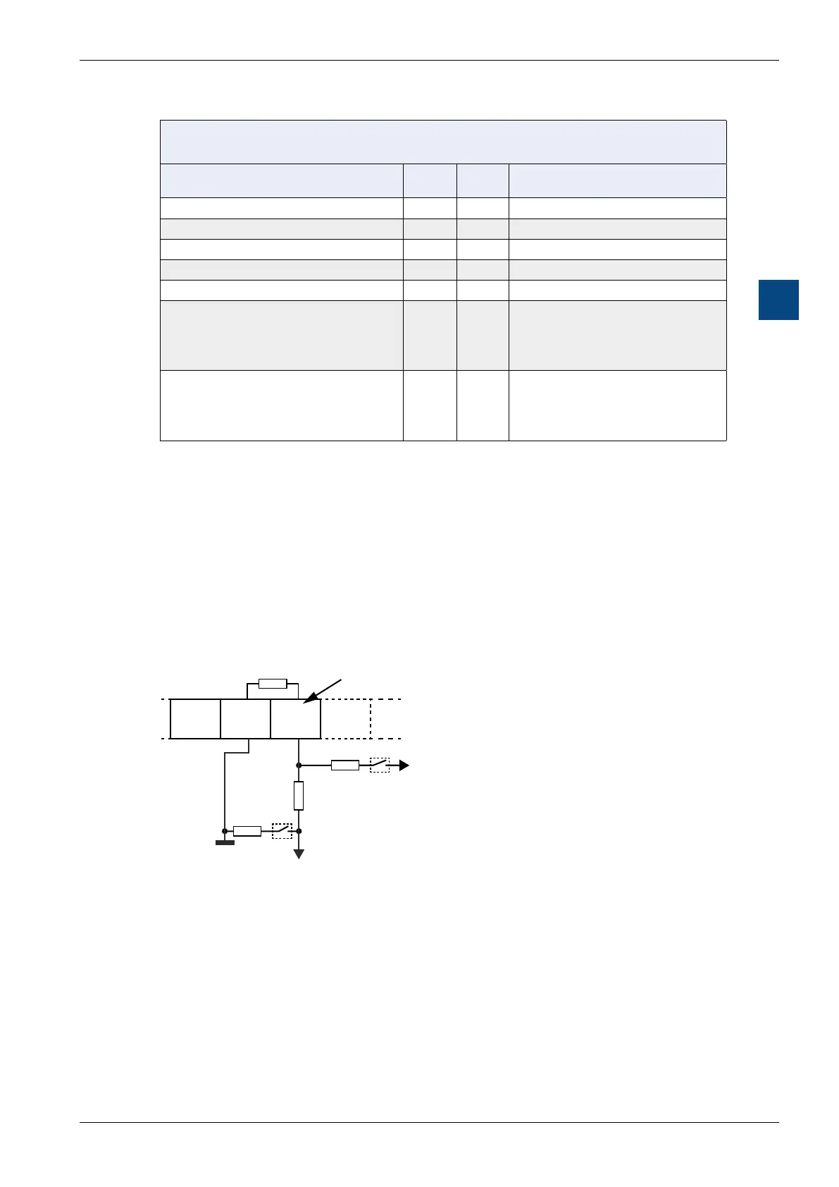
Internal wiring of the universal inputs
Each universal input has a bias resistor.
S2
S1
R
R
UI1GND …UI0
V
UP
SENSOR
DOWN
R
BIAS
ADC
SERIEL
Terminals
Circuit diagram showing universal inputs and bias
resistors.
Legend
S1 + S2 Software switch for PG5 “De-
V 10 V
R Bias resistor (with a resist-
software through S1 to support
0–10 V inputs without bias
R Serial resistor for voltage sepa-
R An internal load resistor (with a
-
pending on the type of sensor
universal inputs.

 Loading...

