7 • DIAGRAMS AND LAYOUTS
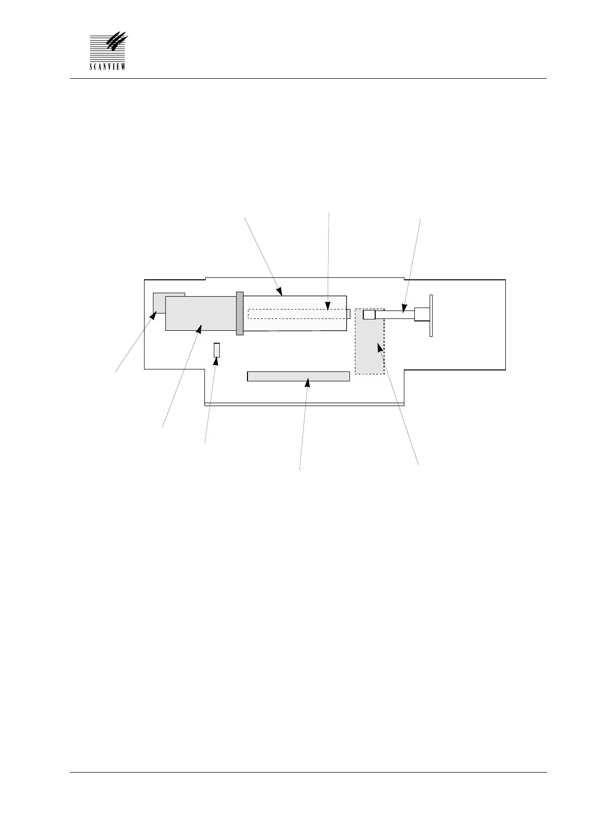
Component Placement Diagram, Front
Edition 1 • January 1996 Service Manual • ScanMate 4000/5000
7•3
A Drum
B Fluorescent tube, main compartment
C Light tube
D Sensor module
E Fluorescent tube, auxilliary compartment
F Indicator display
G DC motor
H Spindle step motor
A
C
D
E
B
G
F
H
Scanner viewed from the front