Service Manual • ScanMate 4000/5000 Edition 1 • January 1996
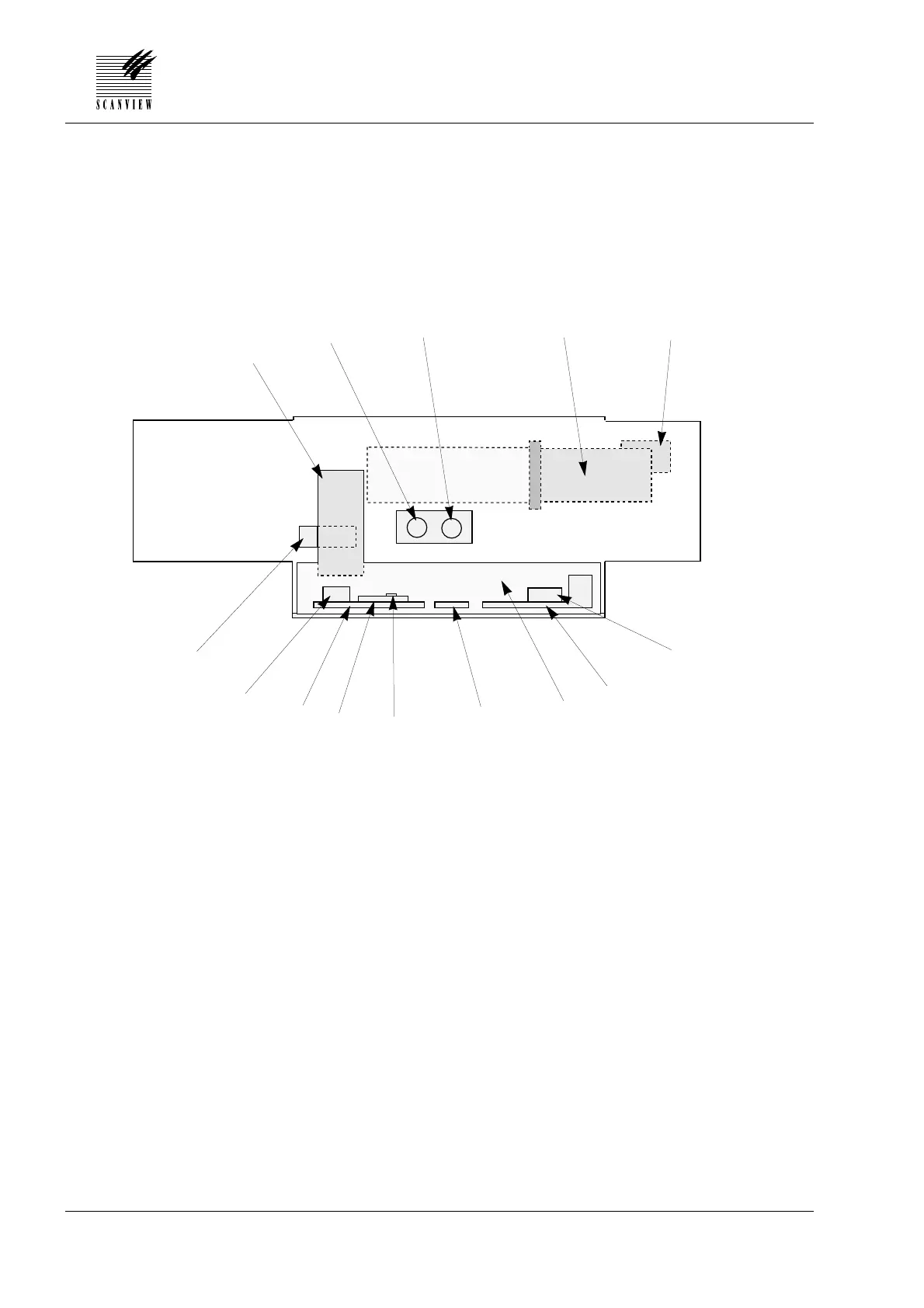
Component Placement Diagram, Back
7•4
7 • DIAGRAMS AND LAYOUTS
A Sensor module
B Reflection lamp
C Transmission lamp
D DC motor
E Spindle step motor
F Booster print board, SM 4000 and SM 5000, (0210 model only)
G Driver board
H Hardware unit
I Bar code board, SM 5000, (0210 model only)
J SCSI controller
K CPU board
L Control board
M Amplifier board (x3)
N PMT module
D
K
M
E
F
G
H
J
A
B
C
I
L
N
Scanner viewed from the back