Safety and Functional Tester GLP2-i/e
During the test, test object and test leads must not be touched!
The safety measures required by law must be adhered to!
Schleich GmbH * D-58675 Hemer * 0049 / (0)2372 / 9498-0 * 0049 / (0)2372 / 9498-99 *
http://www.schleich.com * info@schleich.com 63
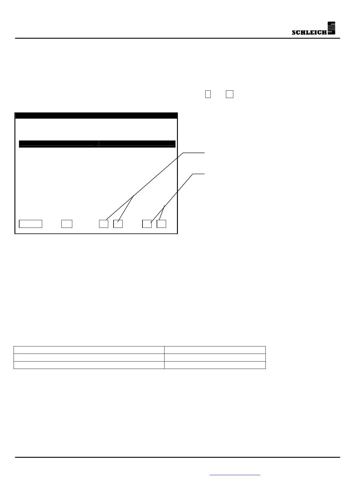
5.8 Time and date (optional)
If the GLP2-i has an internal clock, time and date can be adjusted in this menu.
For adjusting the time or the date, the cursor must be moved (with the arrow buttons) to the point that is
to be adjusted. After this, the time or the date is adjusted with + and - .
Set time and date
13:15:09 Th 28.02.2002
Hour...................:
Minute.................:
Second.................:
Day....................:
Month..................:
Year...................:
Day of the week........:
ESC ?
- +
5.9 Connection diagrams
For simplifying the programming of test processes, the GLP2-i/e allows to administer connection diagrams.
These connection diagrams are possible for every test method. Schleich will program the tables as
discussed with the customer. The connection diagrams allow to control several outputs with one command.
The tables are normally used for the output extension.
Example:
For a HV test process, the outputs 1, 5, 8, 17, 35 are to be set in the first step. For the following test step,
the outputs 2, 4, 9, 17, 35 are required. In the test program, instead of all necessary outputs, only the
variables of the connections need to be entered in the parameters of the high-voltage test.
Definition of the connection (variable) Required outputs
HV at connection 1 1, 5, 8, 17, 35
HV at connection 2 2, 4, 9, 17, 35
Buttons for moving the cursor