Safety and Functional Tester GLP2-i/e
During the test, test object and test leads must not be touched!
The safety measures required by law must be adhered to!
Schleich GmbH * D-58675 Hemer * 0049 / (0)2372 / 9498-0 * 0049 / (0)2372 / 9498-99 *
http://www.schleich.com * info@schleich.com 69
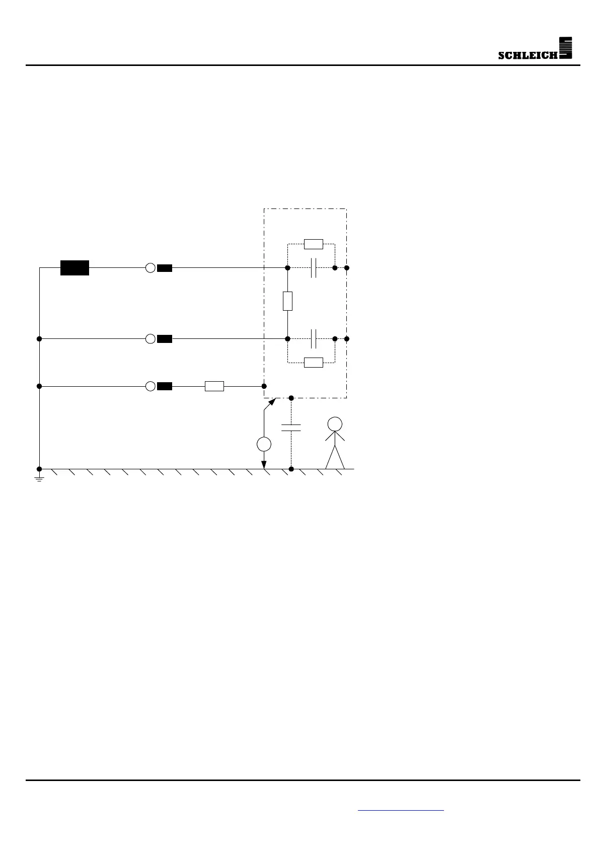
6.0 Test methods
6.1 PE resistance test
6.1.1 Explanations on the PE resistance test
The PE resistance test is used for devices
of protection class I. It is checked,
whether the PE resistance is below a limit
value determined by standards. The
purpose of the test is to find out, whether
possible leakage currents generated in
the test object are correctly discharged to
ground. Faulty PE connections could lead
to a high touch voltage at metallic parts
of the enclosure. If these metallic parts
were touched, the so-called touch current
would be discharged to ground via the
respective person.
It is also possible that later, when
operating the device, the insulation inside
the device gets worse. This could lead to
a short-circuit between the current-
carrying leads and the enclosure of the
device. Through the short-circuit, the
device would be under voltage. In the
worst case, this type of fault could lead to
the enclosure being under mains voltage.
If now somebody touches the device, this
would bear a great risk. By generating a
short-circuit against ground, the PE is
supposed to protect the person. The
generated short-circuit current must
reliably be discharged by the PE against
ground.
For this purpose, a test current that is also determined by standards is lead through the PE. The level of the
test current is normally at least 1.5 times the nominal current of the device. The maximum current level,
however, is limited to 25A ... 30A. The test current produces a voltage drop at the PE, which is measured.
With the level of the test current and the voltage drop, the PE resistance is calculated afterwards.
Un
L
I
L
+ I
abl
I
abl
I
L
N
PE
I
abl
C
k
R
PE
V