3.9 DiggiMEC – Nano HMI with Flag Indicators and Output Relays
The DiggiMEC is a remote HMI to be used in connection with a WIC1 (version 2) protection
relay. (It cannot be used with the predecessor WIC1.)
An overview of the elements and connectors can be found here: ╚═▷ “3.9.1 Navigation –
Operation”, and here: ╚═▷ “3.9.2 DiggiMEC Connectors”
Information about the LEDs and their conguration is here: ╚═▷ “3.8.1 LEDs”
Connection of the DiggiMEC
Network Cable
RJ45
RESET
WIC1
WIC1_Z04
Smart view
DiggiMEC
USB Cable
RJ45
(Rear Side)
Ready
Shortcuts
Device Data
Smart view
Operation
Device planning
Device Para
1,0
Field Para
50/60
Protection Para
7
6
5
WIC1
Operation
Device planning
Device Para
Field Para
Protection Para
Service
File Device Edit View Settings Tools Window Help
- . - - . -
- . - - . -
- . - - . -
- . - - . -
Name Value
- . - - . -
- . - - . -
- . - - . -
- . - - . -
- . -
- . - - . -
- . - - . -
Name
- . -
- . - - . -
- . -
- . -
- . -
- . - - . - - . - - . -
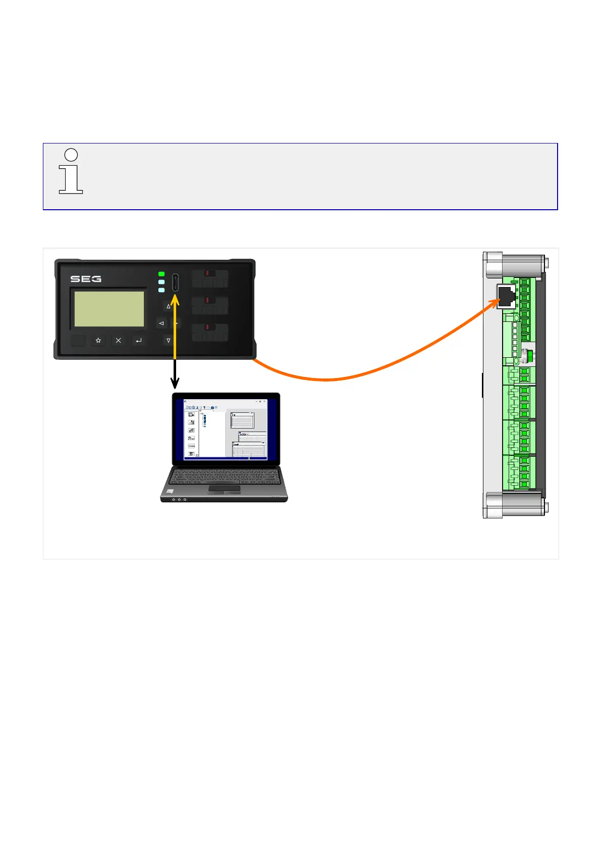
Fig. 34:
Connection options of a WIC1 with a DiggiMEC and a PC.
The WIC1 can be (optionally) connected to the interface device DiggiMEC, which adds
an LCD display, keys and one or three ag indicators. Each ag indicator is mechanically
related to a bistable output relay.
The DiggiMEC can be connected to a Windows PC, so that the parameter setting and
evaluation software Smart view can be used to congure the WIC1 and to retrieve
measurement values and fault data from it. Moreover, the WIC1 can trigger the ag
indicators / output relays.
102 WIC1 WIC1-1.0-EN-MAN
3 Hardware
3.9 DiggiMEC – Nano HMI with Flag Indicators and Output Relays

 Loading...

