3.9.1
Navigation – Operation
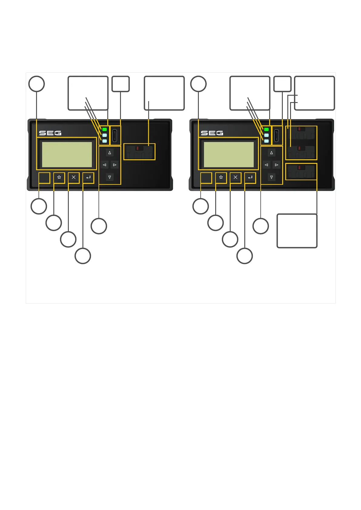
The following illustration shows the elements on the DiggiMEC front:
RESET
4 11
6
7
8
9
10
5
DiggiMEC_Z0D
System-LED
LED2
LED3
3
BO3
2
BO2
RESET
4 11
6
7
8
9
10
5
System-LED
LED2
LED3
1, 2
BO1
DiggiMEC-A DiggiMEC-B
BO2
3.9.1.1 Front Panel Parts
(1), (2), (3) Output Relays / Flag Indicators
Each ag indicator is mechanically connected with a bistable output relay.
(1), (2) The ag indicators BO1, BO2 have one “Form A” (normally open) contact each.
(3) The ag indicator BO3 has a “Form C” (changeover) contact.
• The device variant DiggiMEC‑A has only one bistable output relay BO2.•
• The device variant DiggiMEC‑B has three bistable output relays BO1, BO2, BO3.•
See also ╚═▷ “3.9.2 DiggiMEC Connectors”.
(4) LEDs
The DiggiMEC features three two-colored (red+green) LEDs. The rst (upper) »System« LED
has xed functionality and (roughly) corresponds to the WIC1-LEDs »READY« and »ERROR«.
The »System« LED is constantly green when everything works OK. This means, in particular:
104 WIC1 WIC1-1.0-EN-MAN
3 Hardware
3.9.1 Navigation – Operation

 Loading...

