RJ45
FE
BO2
BO3
DiggiMEC_Z05
Hardware Variant
Option:
DiggiMEC-B
BO3
BO2
BO1
System
LED2
LED3
Rear Side
Front View
Torque:
0.5 Nm
18 234567
BO1
(4.4 lb⋅in)
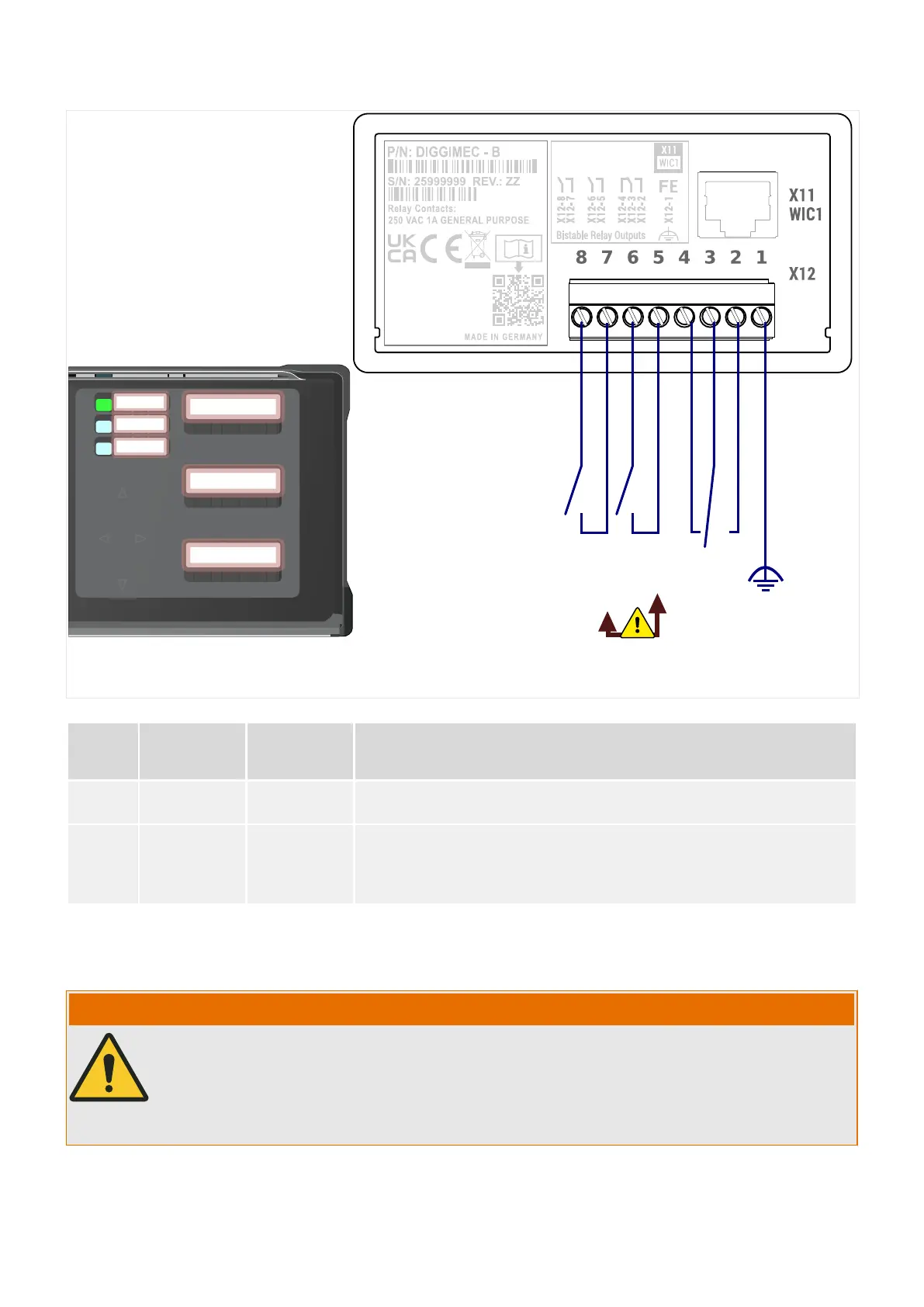
Fig. 37: DiggiMEC‑B: Position of ag indicators and LEDs, and connectors at the rear side.
Slot Max.
Torques of
the Screws
Screw type Description
X12 0.5 Nm
(4.4 lb⋅in)
M3 slotted Connections for functional earth and relay outputs
X11 — — RJ45 connection to the WIC1.
Ethernet CAT3 cable or better, but beware, this is not an Ethernet
connection! Crossover cables must not be used!
Functional Earth (“FE”)
The DiggiMEC must be grounded:
WARNING!
A ground connection (functional earth, min. 2.5 mm² [≤ AWG 13], tightening torque
0.5 Nm [4.4 lb⋅in]) must be connected at the “FE” terminal, see diagram ╚═▷ Fig. 37).
In general, all grounding connections must be low-inductance, i. e. as short as possible,
and national standards – if applicable – must be followed.
116 WIC1 WIC1-1.0-EN-MAN
3 Hardware
3.9.2 DiggiMEC Connectors

 Loading...

