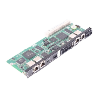
Manual – Controllers DHE/DHF/DHR21B (standard) and DHE/DHF/DHR41B (advanced)
19
4
Installing the DH.21B/41B option in MOVITRAC
®
B / stand-alone unit
Assembly and Installation Notes
4.5 Installing the DH.21B/41B option in MOVITRAC
®
B / stand-alone unit
4.5.1 Description of terminals and LEDs
4.5.2 RS485 interface COM1 connection (connector X24)
The connectors X24 and X34:1/3/5 are connected in parallel. You can connect a
DOP11B operator terminal at X24. If X24 is unassigned, you can connect an operator
terminal or a gearmotor with integrated MOVIMOT
®
frequency inveter to X34:1/3/5.
For more information, refer to "RS485 interface connection (X34)".
INFORMATION
The DH.21B/41B option is installed as described in the "Installation options of DH.21B/
41B" chapter. The option card slot MOVITRAC
®
B and the stand-alone unit provide
additional connections for the DH.21B/41B option. These connections are described
below.
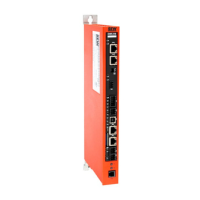
Front view
MOVITRAC
®
B/
stand-alone unit
Designation
LED
Terminal
Function
2108468363
LED H1
H2
Reserved
Reserved
X24 connector:
RS485 COM 1
(RJ10 socket)
X24:4
X24:3
X24:2
X24:1
DGND
RS–
RS+
5V
Reference potential COM 1
Signal RS485–
Signal RS485+
Voltage output DC +5 V
Side view
Stand-alone unit
Designation Terminal Function
2108496651
X26 connector:
CAN 1 and
voltage supply
(plug-in
terminal)
X26:1
X26:2
X26:3
X26:4
X26:5
X26:6
X26:7
CAN 1H
CAN 1L
DGND
Reserved
Reserved
DGND
DC 24 V
System bus CAN 1 high
System bus CAN 1 low
Reference potential control/CAN1
-
-
Reference potential control/CAN1
Voltage supply for controller
X24
H1
H2
2345671
X26
 Loading...
