74
Manual – Controllers DHE/DHF/DHR21B (standard) and DHE/DHF/DHR41B (advanced)
7
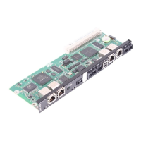
DHR21B/41B option
Technical Data and Dimension Drawings
7.4 DHR21B/41B option
7.5 Stand-alone unit
INFORMATION
Connections identical with those of the DHE21B/41B and DHF21B/41B options are
described chapters "DHE21B/41B option" and "DHF21B/41B option".
DHR21B/41B option
Part number • DHR21B: 1823 610 3
• DHR41B: 1821 632 3
Electrical supply Installed in MOVIDRIVE
®
MDX61B:
• Power consumption: P
max
= 9.5 W
Installed in the MOVIAXIS
®
master module (MXM):
• Power consumption: P
max
= 12 W
Ethernet connection
X30-1, X30-2
Via RJ45 socket, pin assignment according to IEC 11801
Integrated Ethernet switch with autocrossing and autonegotiation functionality.
Engineering Additional engineering access via PROFINET, EtherNet/IP and Modbus TCP/IP interface (X30:1/2)
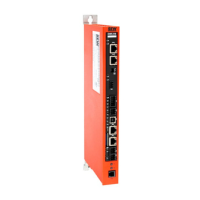
Stand-alone unit
Unit types • DHE21B/41B / UOH11B
• DHF21B/41B / UOH21B
• DHR21B/41B / UOH21B
Electrical supply • X26: U = DC 24 V (–15 % / +20 %)
DGND must be grounded (PELV)
• Power consumption P
max
= 8.5 W, I
max
= 600 mA
• X31: You must supply the binary inputs and outputs separately with DC 24 V.
INFORMATION
Note the following:
• The CAN 1 system bus is connected in parallel to X33 and X26.
• The RS485 interface COM1 is connected in parallel to X34 and X24.
• The remaining technical data is identical to that in chapters 7.1 and 7.2.
 Loading...
