36
Manual – Controllers DHE/DHF/DHR21B (standard) and DHE/DHF/DHR41B (advanced)
4
Installing the DHF21B/41B option
Assembly and Installation Notes
Setting the station
address
To set the DeviceNet station address, use DIP switches 2
0
– 2
5
on the DHF21B/41B
option. The DHF21B/41B option supports address range 0 – 63.
Setting the MAC ID The MAC ID (Media Access Control Identifier) is set on the DHF21B/41B option using
DIP switches 2
0
– 2
5
in a binary coded manner. The MAC ID represents the node
address of the DHF21B/41B option. The DHF21B/41B option supports address range
0–63.
Setting the baud
rate
The baud rate is set using DIP switches 2
6
and 2
7
.
A maximum of 64 DeviceNet data words can be exchanged between the DeviceNet
module and the DHF21B/41B option. The number is set using the DeviceNet scanner.
4.8.5 LEDs in DeviceNet mode
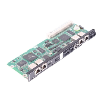
The DHF21B/41B option card comes equipped with four two-color LEDs for diagnostics
of the DeviceNet system. They indicate the current state of the DHF21B/41B option and
the DeviceNet system. The unit state indicated by the LEDs is described in the "Error
diagnostics" section.
INFORMATION
Always de-energize the DHF21B/41B option before changing the DIP switch setting.
DIP switch settings are adopted during initialization only.
2103383051
2
0
–2
5
= MAC ID setting
2
6
–2
7
= Baud rate setting
 Loading...
