Manual – Controllers DHE/DHF/DHR21B (standard) and DHE/DHF/DHR41B (advanced)
23
4
Installing the DH.21B/41B option
Assembly and Installation Notes
4.7 Installing the DH.21B/41B option
4.7.1 Functional description of terminals, DIP switches and LEDs
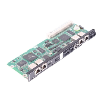
Front view
DH.21B/41B
option
Designation
LED
DIP switch
Terminal
Function
2102456075
LED LED 10
LED 9
LED 8
LED 7
LED 6
LED 5
LED 4
LED 3
LED 2
LED 1
24 V / I/O OK
DIO0/1
DIO2/3
DIO4/5
DIO6/7
User LED
PLC state
IEC progr. state
CAN 2 state
CAN 1 state
State of voltage supply I/O
State of input or output DIO 0/1
State of input or output DIO 2/3
State of input or output DIO 4/5
State of input or output DIO 6/7
Freely programmable
State of control firmware
State of control program
State of CAN 2 system bus
State of CAN 1 system bus
Terminal X31:
Binary inputs and outputs
(plug-in terminals)
X31:1
X31:2
X31:3
X31:4
X31:5
X31:6
X31:7
X31:8
X31:9
X31:10
+24 V input
BZG 24 V
DIO 0
DIO 1
DIO 2
DIO 3
DIO 4
DIO 5
DIO 6
DIO 7
Voltage input DC +24 V
Reference potential for binary signals
Binary input or output (DIO 0)
Binary input or output (DIO 1)
Binary input or output (DIO 2)
Binary input or output (DIO 3)
Binary input or output (DIO 4)
Binary input or output (DIO 5)
Binary input or output (DIO 6)
Binary input or output (DIO 7)
Terminal X34:
RS485 interfaces COM1, COM2
(plug-in terminals)
X34:1
X34:2
X34:3
X34:4
X34:5
X34:6
RS+
RS+ insulated
RS–
RS– insulated
DGND
GND insulated
Signal RS485+ (COM 1)
Signal RS485+ insulated (COM 2)
Signal RS485– (COM 1)
Signal RS485– insulated (COM 2)
Reference potential (COM 1)
Reference potential (COM 2)
X35 terminal:
USB connection
X35:1
X35:2
X35:3
X35:4
USB +5 V
USB–
USB+
DGND
Standard USB-B assignment
X36 terminal:
Ethernet 1 connection
System bus (RJ45 socket)
X36
Standard Ethernet assignment
X37 terminal:
Ethernet 2 connection
(RJ45 socket)
X37
X32 terminal:
CAN 2 system bus
(electrically isolated)
(plug-in terminals)
X32:1
X32:2
X32:3
BZG_CAN 2
CAN 2H
CAN 2L
Reference potential for system bus
CAN 2
System bus CAN 2 high
System bus CAN 2 low
X33 terminals:
C
AN 1 system bus
(plug-in terminals)
X33:1
X33:
2
X33:3
DGND
CAN 1H
CAN 1L
Reference potential for system bus
CAN 1
System bus CAN 1 high
System bus CAN 1 low
DIP switch S1
Up
Down
Default IP address (192.168.10.4)
IP parameter from SD memory card
 Loading...
