Manual – IPOSplus®
101
7
Position detection with MQx
Position Detection via Binary Inputs
7.5.6 Counter
The MQx modules have a counter that can be connected to either DI0 or DI1. The pos-
itive edges are counted to a maximum input frequency of 4 kHz. You must change the
setting of the corresponding input to "MQX ENCODER IN" to activate the counter func-
tion. This setting switches off the input filter automatically. As a result, the input signal
for the counter must be fault-free and bounce-free. The value of the counter is written to
variable H511.
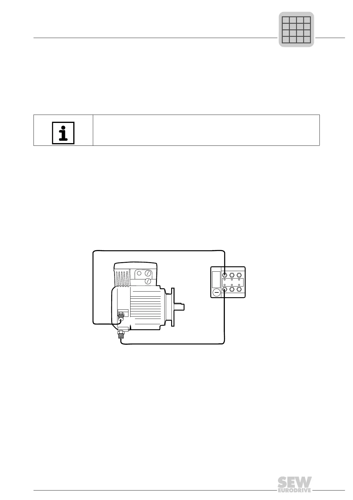
7.5.7 Connecting the built-in encoders
The cabling of the built-in encoders can be checked using the LEDs of the MQx. When
a motor turns slowly, the LEDs at inputs DI0 and DI1 flash.
Connecting the
NV26 proximity
sensor
To connect the NV26 built-in encoders (proximity sensors), refer to the "Drive System
for Decentralized Installation – PROFIBUS Interfaces, Field Distributors" manual.
Two simple 4-pole, shielded sensor cables with plug and M12 socket are required for
connection. The cable connects the NV26 proximity sensors to DI0 and DI1 of the bus
module.
We recommend you use metal M12 plug and sockets and connect the shielding at both
ends.
If the MQx interface counts the motor position in H511 in the wrong direction, the M12
plugs at inputs DI0 and DI1 must be exchanged.
Connecting the
EI76, ES16 incre-
mental encoder
To connect the EI76 and ES16 built-in encoders, refer to the "Drive System for
Decentralized Installation – PROFIBUS Interfaces, Field Distributors" manual.
INFORMATION
If both the inputs DI0 and DI1 are set to "MQX ENCODER IN", the proximity sensor
evaluation is activated automatically and the counter function is switched off.
480466315
 Loading...