116
Manual – IPOSplus®
9
Synchronous operation with technology option "Cam"
IPOSplus
®
and Synchronized Motion
•IPOS
plus®
variables H360 to H450 are reserved for synchronous operation and
should not be used in the application program see section "Overview of System
Variables (page 29)".
• Synchronous operation is controlled using IPOS
plus®
variables within an IPOS
plus®
program. All states of synchronous operation can be viewed and set in the variable
range for synchronous operation from H360 to H450.
• ISYNC startup is supported by a graphical user interface.
• Slave is not subject to slip (only with MOVIDRIVE
®
A).
For more detailed information, refer to the "Internal Synchronous Operation (ISYNC)"
manual.
9.5 Synchronous operation with technology option "Cam"
A master movement is usually represented as a machine angle between 0 and 360 de-
grees. A number of curve points are defined with reference to this machine angle (the
"Movement plan"). These control points specify the position of the particular slave drive
with reference to the master.
The master drive can either be a physical drive or a virtual master encoder. The master
encoder can also be switched over using the synchronized system bus (SBus). The re-
lationship between the positions of the master drive and the slave drive is often specified
in a 2-dimensional graph. The position of the master drive is entered along the horizontal
axis and the position of the slave drive along the vertical axis. The range of positions
along the horizontal axis is referred to as the master cycle, the range of positions along
the vertical axis as the slave cycle.
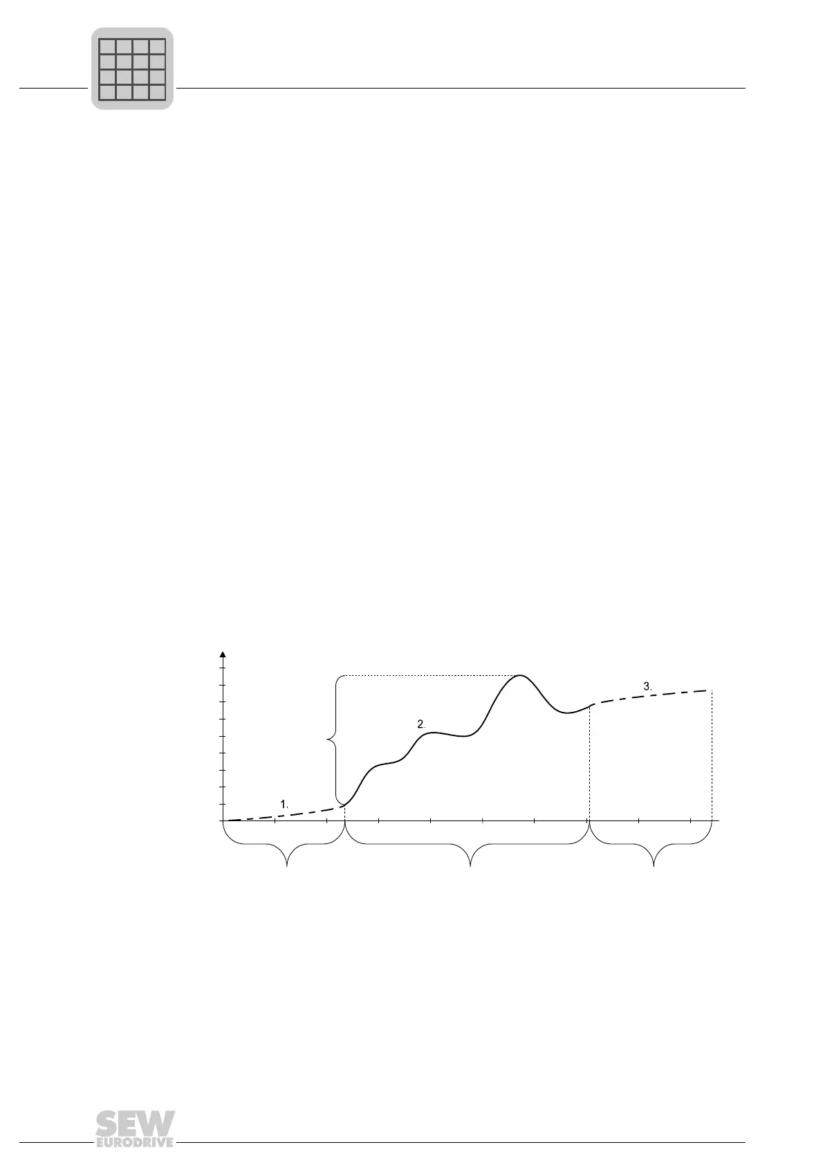
Electronic cam:
478837771
[1] Startup cycle is run through once
[2] Master cycle is repeated cyclically
[3] Stop cycle is run through once
[4] Slave cycle
s1 Master length
s2 Slave length
Slave length
Slave
cycle
Master length
Startup cycle
is completed once
Master cycle
is continued cyclically
Stop cycle
is completed once
 Loading...