58
Manual – IPOSplus®
6
External encoder (X14)
Position Detection and Positioning
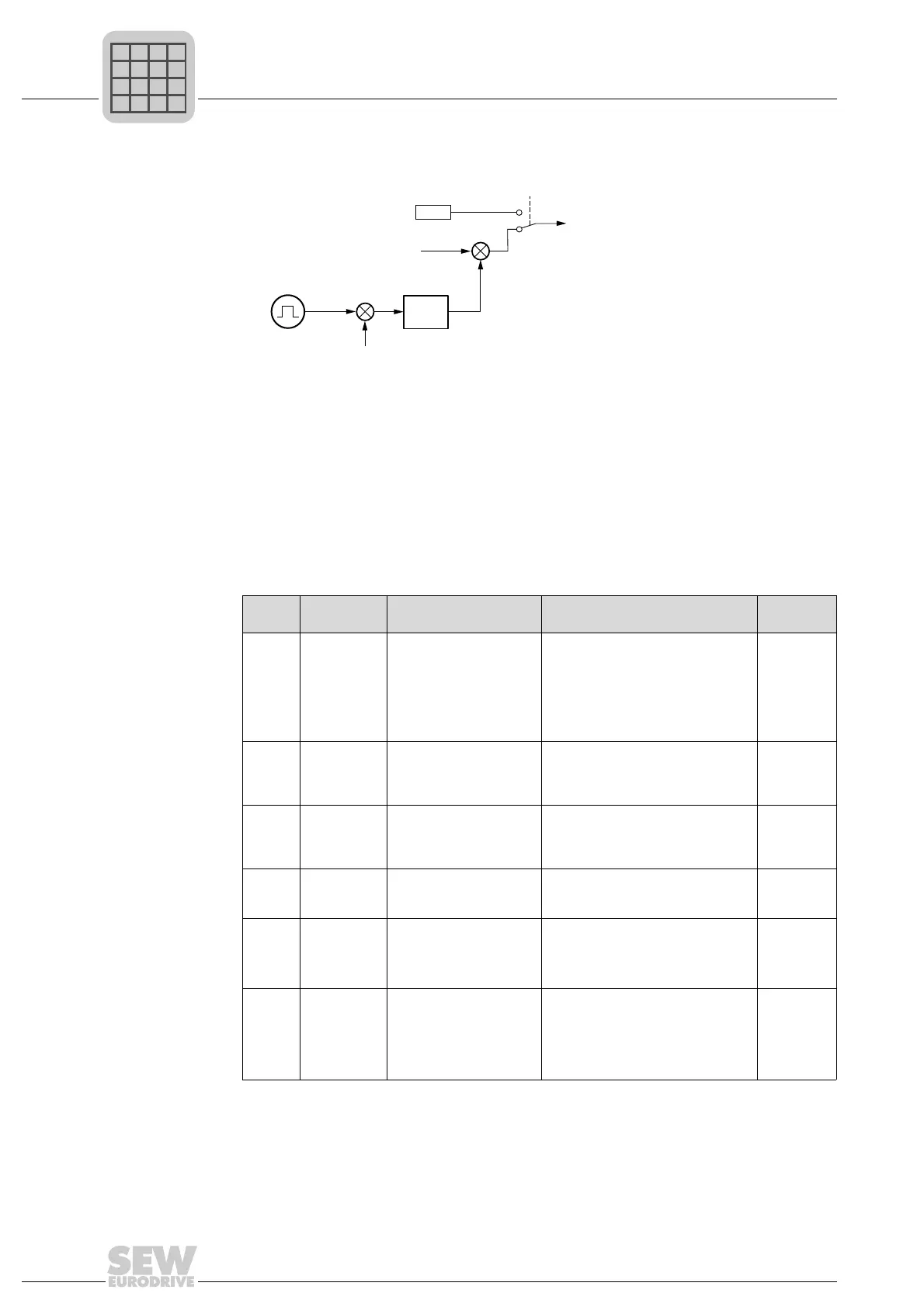
The following block circuit diagram applies:
Set the following parameters for the external encoder:
476710667
P
x
= Non-linearized position value of encoder
P
act
= Actual position value for ramp generator and position controller
P941 = Actual position source
P942 = Encoder factor numerator
P943 = Encoder factor denominator
P944 = Encoder scaling external encoder
H510 = External encoder with actual value on variable
H511 = Motor encoder with actual value on variable
Table 2: Parameter settings for the trolley
Num-
ber
Designation Function Setting Range
P944 Encoder
scaling ext.
encoder
Multiplies the encoder
signals with the set value
Highest value that is smaller than the
ratio between the resolution of the
motor encoder and the external
encoder.
Example: Motor encoder: 4096 Inc. /
ext. encoder 800 inc. = 5.12. Value:
4.
Fixed: 1, 2,
4, 8, 16, 32,
64
P943 Encoder fac-
tor denomi-
nator
Denominator to deter-
mine the ratio between
the motor encoder and
the ext. encoder.
Number of increments (in H511, to
read ACTPOS. MOT) for a certain
distance s.
max. 32767
P942 Encoder fac-
tor numerator
Numerator to determine
the ratio between the
motor encoder and the
ext. encoder.
Number of increments (in H510, to
read the ACTPOS. EXT) for a certain
distance s, as for P943.
max. 32767
P941 Source
actual posi-
tion
Actual position value for
IPOS
plus®
position con-
troller
Ext. encoder X14 (Selection)
P945 Synchro-
nous
encoder type
(X14)
Selects encoder type Depends on the encoder that is con-
nected.
TTL
SIN/COS
HIPER-
FACE
P946 Synchro-
nous
encoder
counting
direction
(X14)
Inversion of the direction
of rotation of the encoder
Set so that the counting direction of
the motor encoder = counting direc-
tion of the external encoder.
NORMAL
INVERTED
EXT
P
act
P943
P944
P942
H511
P941
H510