76
Manual – IPOSplus®
6
Modulo function
Position Detection and Positioning
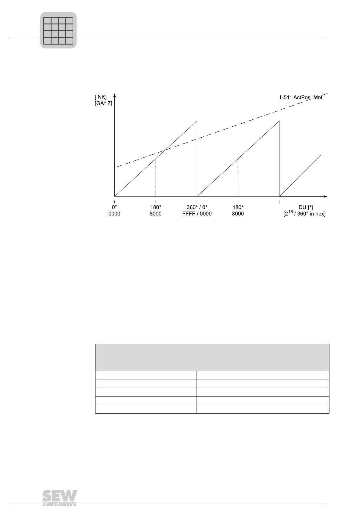
The diagram below shows the relationship between the current position of the IPOS
plus®
encoder, for example, the motor encoder H511 and the actual position in the modulo
representation. The actual modulo position always moves within the output unit, for ex-
ample, from 0° (= 0 increments) to 360° (= 2
16
increments).
A new target position is specified by writing the IPOS
plus®
variable H454 MODTAGPOS
in 32-bit format.
The system software differentiates between 2 forms of representation, which can be set
in H453, bit 1:
• 360° = 16 bit (referred to below as "2
16
/360°" ) standard setting: In this case, the
higher value bit range can be used for specifying whole number 360° rotations.
• 360° = 32 bit (referred to below as "2
32
/360°" ) standard setting: This notation should
be avoided due to the restriction on the maximum range of representation. If used,
the product of modulo numerator and modulo encoder resolution corresponds to one
360° revolution.
Sample position selection in output units (in hexadecimal format):
477219595
Representation of several integral revolutions
H454 MODTAGPOS = k × 360° + 0 ... 360° = k × 2
16
+ 0 ... (2
16
-1)
Representation of one integral revolution
H454 MODTAGPOS = 0 ... 360°
Target position in output unit [ ° ] Realization via IPOS
plus®
variable H454 MOD.TAGPOS
360° 0001 0000
3 × 360° 0003 0000
180° 0000 8000
270° 0000 C000